Do you have a question about the Rigol DHO1000 Series and is the answer not in the manual?
Provides essential safety precautions for operating the instrument safely and avoiding hazards.
Explains warning, caution, and danger notices and their corresponding symbols used in the manual.
Defines measurement categories and specifies the instrument's applicable category for safe usage.
Guides users through initial checks of packaging, instrument, and accessories after unboxing.
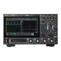
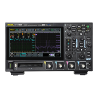
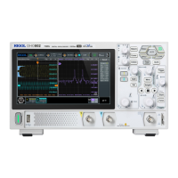
Shows the front and side views of the instrument with physical dimensions.
Covers initial setup steps, including tilting, power connection, and turn-on checkout.
Details the components and controls found on the front panel of the oscilloscope.
Describes the connectors and ports located on the rear panel of the oscilloscope.
Explains the different elements and areas of the oscilloscope's graphical user interface.
Explains how to use touch gestures like tap, pinch&stretch, and drag for operation.
Outlines methods for setting parameters using knobs and the touch screen keypad.
Guides on activating or deactivating analog input channels for signal display and measurement.
Explains how to set the vertical scale (V/div) to adjust waveform amplitude display.
Details how to adjust the vertical offset to position the waveform relative to the display center.
Describes how to select coupling modes (DC, AC, GND) to filter signal components.
Explains how to use the bandwidth limit function to reduce noise in waveforms.
Guides on setting the probe attenuation ratio and deskew for accurate measurements.
Explains how to adjust the horizontal time base (s/div) to control waveform expansion/compression.
Details how to adjust the horizontal position (trigger point) to move waveforms left or right.
Describes how to use zoom mode to horizontally expand specific waveform sections for detailed viewing.
Explains different acquisition modes (Normal, Average, Peak, High Res, UltraAcquire) for waveform capture.
Describes the real-time sampling mode and its display indicators.
Explains the process of sampling and its effects on waveform display and data.
Defines memory depth and its relation to waveform storage capability and acquisition memory.
Explains how to set the reference point for horizontal waveform expansion or compression.
Describes the roll mode for continuous waveform display from right to left.
Explains how to enable and configure XY mode for voltage-voltage display.
Explains how to select trigger sources such as analog channels, AC Line, or external trigger.
Details how to adjust the trigger level to define the point at which a trigger occurs.
Describes trigger modes like Auto, Normal, and Single for controlling acquisition behavior.
Explains trigger coupling options (DC, AC, LFR, HFR) for filtering the trigger signal.
Details the trigger holdoff function to stabilize triggering on complex waveforms.
Explains how to use noise rejection to reduce false triggers caused by noise.
Introduces various trigger types available for capturing specific signal events.
Triggers based on signal slope (rising, falling, or either) at a specified level.
Triggers when a pulse meets specific positive or negative width conditions.
Triggers based on the time it takes for a signal's slope to cross trigger levels.
Triggers when the time interval between signal edges exceeds a preset timeout value.
Triggers on specific RS232 serial protocol events like start frame or data.
Triggers on specific I2C serial bus events like start, stop, or address conditions.
Triggers based on SPI bus signals like chip select, clock, data, and mode.
Triggers on CAN bus signals like frame start, end, type, or errors.
Triggers on LIN bus signals like sync field, identifier, data, or frame.
Explains the functionality of the AUX OUT connector for trigger and pass/fail signals.
Describes how to perform basic arithmetic operations (A+B, A-B, A*B, A/B) on waveforms.
Explains various mathematical functions like Intg, Diff, Sqrt, Lg, Ln, Exp, Abs, AX+B.
Details the Fast Fourier Transform function for analyzing frequency spectrum of signals.
Explains how to perform logic operations (AND, OR, XOR, NOT) on digital signals.
Describes the use of digital filters (LowPass, HighPass, BandPass, BandStop) for signal processing.
Guides on using the auto-scale function for automatic waveform display and measurement setup.
Explains how to perform automatic measurements for waveform parameters.
Details how to set measurement sources and parameters for auto measurements.
Shows how to select specific measurement items from Vertical, Horizontal, and Other categories.
Explains how to use cursors (X and Y) for manual measurement of waveform values.
Guides on manually adjusting cursors to measure waveform points.
Explains using track mode where cursors automatically follow waveform points.
Describes using cursors in XY mode to measure waveform amplitude.
Details the instrument's built-in Digital Voltmeter for 4-digit voltage measurements.
Covers DVM source selection, mode (AC RMS, DC), and limit settings.
Describes the frequency counter function for measuring frequency, period, and edge counts.
Covers frequency counter source selection and resolution settings.
Guides on how to access and enable the reference waveform function.
Explains how to select the source, save, and clear reference waveforms.
Details adjusting vertical scale, offset, color, and label for reference waveforms.
Covers saving and loading reference waveforms to/from internal or external memory.
Explains how to enable or disable the pass/fail test and set up basic functions.
Guides on selecting the signal source channel for the pass/fail test.
Details how to define custom masks for pass/fail criteria by setting tolerance ranges.
Explains configuring output events and actions (e.g., Aux Out, error action) upon test completion.
Describes how to start, stop, and monitor the pass/fail test process.
Explains how to view pass/fail test statistics like failed/passed/total frames.
Explains decoding for parallel bus signals, including clock and data line settings.
Details decoding for RS232 serial communication, including source, data package, and parity settings.
Explains decoding for I2C serial bus, covering clock/data sources and address/data conditions.
Details decoding for SPI serial bus, including clock, MISO/MOSI sources, and mode settings.
Explains decoding for CAN bus signals, including signal type, baud rate, and sample position.
Covers decoding for LIN bus signals, including protocol version, baud rate, and parity bits.
Guides on adding diagram windows like XY or Math for simultaneous display.
Explains adding result table windows for measurements or decoded data.
Covers enabling waveform recording and setting common parameters.
Details options for waveform recording, including interval, frames, and max frames.
Explains how to play back recorded waveforms using different modes and sequences.
Guides on using the search function to find specific events like edges or pulse widths.
Explains navigating through time, search events, and segments of acquired waveforms.
Describes the "Vector" display mode for vivid waveform representation.
Explains adjusting persistence time to view waveform changes at different refresh rates.
Details how to adjust the brightness of the displayed waveforms.
Guides on enabling or disabling the screen grid (FULL, HALF, NONE).
Covers settings for grid brightness and window transparency.
Explains how to enable or disable the display of the scale on the screen.
Describes enabling or disabling color grade display for acquisition probability.
Explains the waveform freeze function to capture and display static waveforms.
Guides on accessing the storage menu for saving, loading, and upgrading.
Details how to save instrument setups, waveforms, and screen images.
Explains saving the screen image in various formats like PNG or JPG.
Guides on saving waveform data in formats like BIN or CSV.
Details saving the oscilloscope's current configuration settings.
Describes the structure and content of binary data files.
Explains loading setups or waveforms from internal or external memory.
Covers local and online methods for upgrading the instrument's firmware.
Explains operations for managing files and folders on storage devices.
Configures network status, IP settings (DHCP, Static), MAC, and VISA addresses.
Displays prompts indicating the current network connection status.
Sets IP address configuration to DHCP, Auto IP, or Static IP.
Details basic settings like system language and power status.
Explains the auto configuration function for optimizing signal display and channel settings.
Details the self-calibration procedure for ensuring measurement accuracy.
Describes how to view and install optional instrument features.
Covers configuring the front-panel quick action key for common operations.
Explains how to perform self-checks for keys, touch screen, and display.
Guides on connecting and controlling the instrument remotely via USB using PC software.
Explains remote control via LAN using network connection and web browser.
Details remote control via GPIB interface, including driver installation and address setup.
Provides solutions for power-on issues where the display remains black.
Offers steps to diagnose and resolve issues with no waveform display on the screen.
Lists troubleshooting steps for USB storage device recognition problems.
Provides solutions for issues where the touch screen functionality is not working.
Lists available instrument models, standard accessories, and upgrade options with order numbers.
Outlines the product warranty terms and conditions provided by RIGOL.
Provides a comprehensive table of the instrument's default factory settings for various parameters.
| Digital Channels | 16 (Optional) |
|---|---|
| Vertical Resolution | 12-bit |
| Memory Depth | 50 Mpts (per channel) |
| Waveform Capture Rate | 1, 000, 000 wfms/s |
| Interfaces | USB, LAN, HDMI |
| Input Impedance | 1 MΩ ± 1% |
| Trigger Types | Edge, Pulse, Video, Slope, Window, Runt, Pattern |
| Protocol Decoding | I2C, SPI, UART, CAN, LIN |
| USB Ports | USB Host, USB Device |
| Analog Channels | 4 |