5.4 To Specify Channel Coupling
You can remove unwanted signals by setting the coupling mode. For example, the
signal under t
est is a squar
e waveform with DC offset.
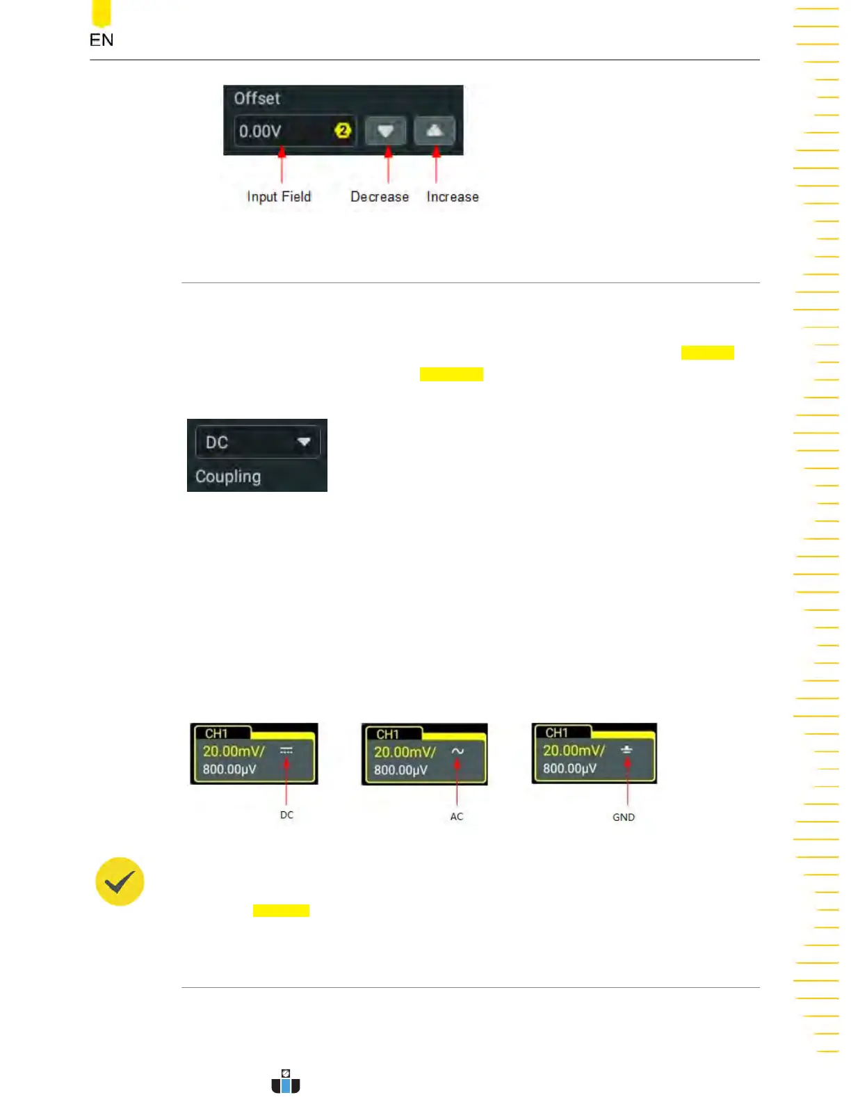
Click or tap the channel status label at the bottom of the screen. Then the
Vertical
menu is display
ed. Click or tap the
Coupling dr
op-down butt
on to select the coupling
mode.
• When the coupling mode is "DC", both the DC and A
C components o
f the signal
under test can pass the channel.
• When the coupling mode is "AC", the DC components of the signal under test
are blocked.
• When the coupling mode is "GND", the DC and AC components of the signal
under test are blocked.
After a coupling mode is selected, it is indicated in the channel status label at the
bottom of the screen, as shown in the figure below.
TIP
When the input impedance is set to "50
Ω", the channel coupling is set to DC coupling by
force. The
Coupling menu item is gray
ed out and cannot be modified.
5.5 To Specify Bandwidth Limit
This series oscilloscope supports the bandwidth limit function. Setting the bandwidth
limit can reduce the noises in the display
ed waveforms. For example, the signal under
test is a pulse with high frequency oscillation.
Vertical System
Copyright ©RIGOL TECHNOLOGIES CO., LTD. All rights reserved.
DHO1000 User Guide
43
www.calcert.com sales@calcert.com1.888.610.7664
0
5
10
15
20
25
30
 Loading...