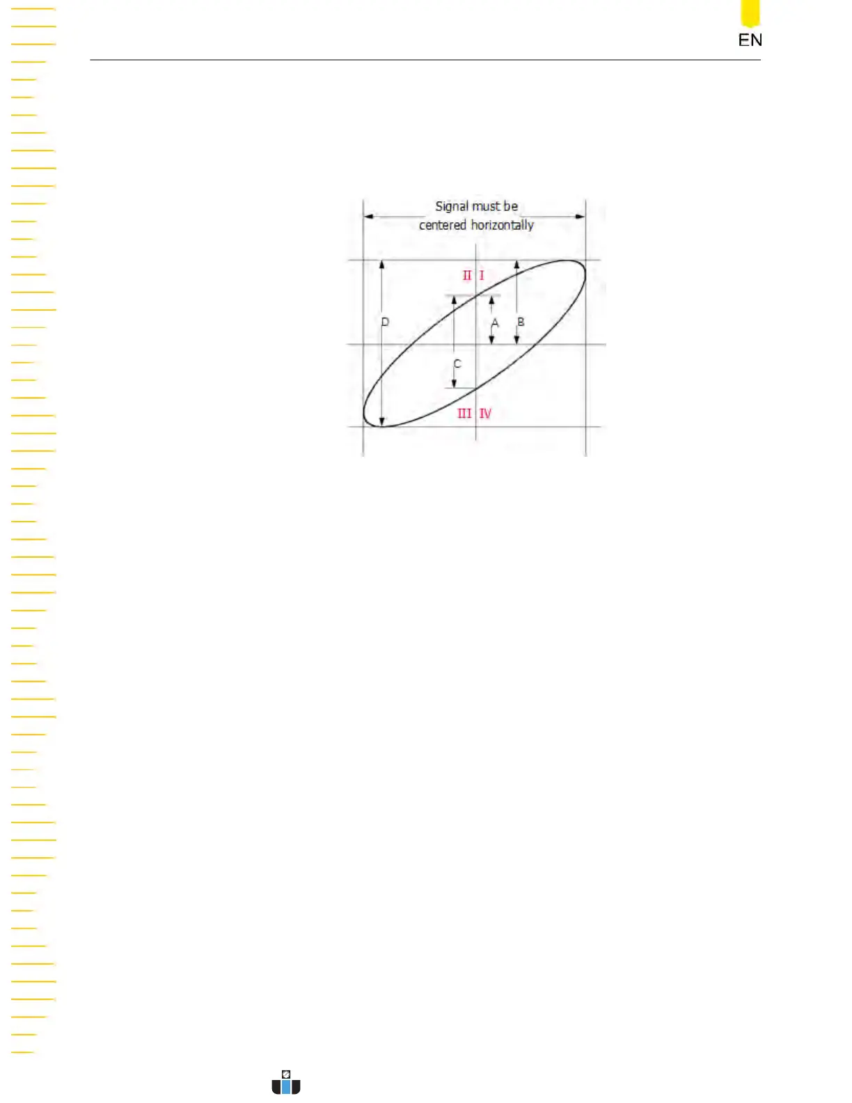
Phase Deviation Measurement
In this mode, you can use the Lissajous method t
o measure the phase deviation of the
two input signals whose frequencies are the same. The following figure shows the
measurement schematic diagram of phase deviation.
Figure 7.5 Measurement Schematic Diagram of Phase Deviation
According t
o sinƟ = A/B or C/D, Ɵ is the phase deviation angle between the two
channels. The definitions of A, B, C, and D are shown in the figure above. The phase
deviation angle is obtained, that is:
Ɵ=±arcsin(A/B) or ±arcsin(C/D)
If the principal axis of the ellipse is within Quadrant I and III, the phase deviation
angle obtained should be within Quadrant I and IV, namely within (0 to π/2) or (3π/2
to 2π). If the principal axis of the ellipse is within Quadrant II and IV, the phase
deviation angle obtained should be within Quadrant II and III, namely within (π/2 to
π) or (π to 3π/2).
The XY mode can be used to measure the phase deviation occurred when the signal
under test passes through a circuit network. Connect the oscilloscope to the circuit to
monitor the input and output signals of the circuit.
Acquisition System
DHO1000 User Guide
64
Copyright ©RIGOL TECHNOLOGIES CO., LTD. All rights reserved.
www.calcert.com sales@calcert.com1.888.610.7664
0
5
10
15
20
25
30
 Loading...