Do you have a question about the Rigol DHO924 and is the answer not in the manual?
Safety precautions for instrument operation and avoiding hazards.
Explains warning and caution symbols and their meanings.
Steps for inspecting packaging, the instrument, and accessories upon receipt.
Covers initial setup steps before operating the oscilloscope.
Details on connecting the oscilloscope to an AC power source using the provided adapter.
Describes the self-test process after powering on the instrument.
Guidance on connecting passive and optional logic probes to the oscilloscope.
Steps for performing a function inspection and restoring default settings.
Procedure for compensating the oscilloscope probe for accurate measurements.
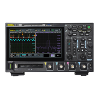
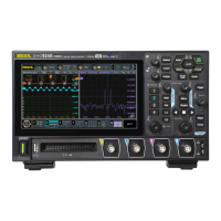
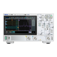
Details the components and features of the oscilloscope's front panel.
Describes the connectors and features on the rear panel of the oscilloscope.
Explains the different elements and areas of the oscilloscope's graphical user interface.
Steps to turn analog channels (CH1-CH4) on or off for signal acquisition.
How to modify the vertical scale (Volts/division) for waveform amplitude display.
Procedure for adjusting the vertical position of waveforms relative to the screen center.
Configuration for probe attenuation ratios to ensure accurate measurements.
How to set the time per division for horizontal waveform display.
Procedure for adjusting the horizontal position of waveforms relative to the display center.
How to enable zoom mode for horizontally expanding waveform details.
Details the Normal, Average, Peak, and UltraAcquire acquisition modes.
Explains sampling process and effects of low sample rates on waveforms.
Describes memory depth and its relationship with sample rate and horizontal time base.
How to select analog or digital channels as trigger sources.
How to adjust trigger level/threshold for analog and digital channels.
Explanation of Auto, Normal, and Single trigger modes.
Overview of available trigger types like Edge, Pulse Width, Slope, etc.
How to trigger on specific edges (rising, falling, either) of an input signal.
How to trigger based on the width of positive or negative pulses.
How to trigger based on the slope of signal edges.
How to trigger based on a specified logical pattern across multiple channels.
How to trigger based on the duration of a specified pattern.
How to trigger when the signal remains idle for a preset timeout value.
How to trigger on pulses that cross one trigger level but not another.
How to trigger when a signal passes through high or low trigger levels.
How to trigger based on the time difference between edges of two sources.
How to trigger based on setup or hold time relative to a clock signal.
How to trigger on the Nth edge after a specified idle time.
How to trigger on RS232 serial communication events like start frame or errors.
How to trigger on I2C bus events like start condition, address, or data.
How to automatically configure the oscilloscope for optimal signal display and measurement.
Covers automatic measurements for waveform parameters and statistics.
Details how to set measurement sources and enable various waveform parameters.
How to use cursors to measure X and Y axis values of waveforms.
How to manually adjust cursors to measure waveform values.
How to use cursors to track waveform points automatically across different sources.
How to enable and use the 4-digit digital voltmeter for voltage measurements.
How to enable and use the frequency counter for frequency, period, and edge event measurements.
How to configure frequency counter source and resolution.
Steps to enable or disable individual or groups of digital channels.
How to set logic threshold levels for digital channels to distinguish logic 1 and 0.
How to enable or disable the histogram analysis function.
How to output basic waveforms like Sine, Square, Ramp, DC, and Noise.
How to enable/disable Bode plot, start/stop operation, and set sources.
Steps to enable or disable the Bode plot function.
How to start, stop, or pause the Bode plot drawing operation.
Steps to access and enable the reference waveform function.
How to enable or disable the pass/fail test function and set output options.
How to self-define or import/export masks for pass/fail criteria.
How to start, stop, and view pass/fail test results and statistics.
Covers settings for waveform recording and playback functions.
How to enable waveform recording and set parameters like interval and frames.
Covers saving images, waveforms, and setups to memory or USB.
Procedure for performing self-calibration to ensure precise measurements.
Steps for connecting and controlling the instrument remotely using a USB connection.
Steps for connecting and controlling the instrument remotely using a LAN connection.
| Bandwidth | 200 MHz |
|---|---|
| Channels | 4 |
| Vertical Resolution | 12-bit |
| Waveform Capture Rate | 1, 000, 000 wfms/s |
| Vertical Sensitivity | 1 mV/div to 10 V/div |
| Timebase Range | 1 ns/div to 1000 s/div |
| Serial Bus Triggering and Decoding | I2C, SPI, UART, CAN, LIN, FlexRay |
| Input Impedance | 1 MΩ ± 1% || 16 pF ± 3 pF |
| Protocol Decoding | I2C, SPI, UART, CAN, LIN, FlexRay |
| FFT Points | 1 Mpts |
| Operating System | Linux |
| Connectivity | USB, LAN, HDMI |
| Display | 10.1-inch capacitive touchscreen, 1280x800 resolution |
| Trigger Types | Edge, Pulse, Slope, Video, Runt, Window, Pattern, Serial |
| Interfaces | USB Host, USB Device, LAN, HDMI, AUX |
| Max Input Voltage | 400 V (DC + AC peak) |