Do you have a question about the Rigol DHO900 Series and is the answer not in the manual?
Covers essential safety precautions to prevent injury and equipment damage.
Explains warning, caution, and danger notices and their corresponding safety symbols.
Defines measurement categories and their applicability to instrument usage.
Details procedures for inspecting packaging, instrument, and accessories.
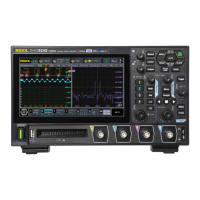
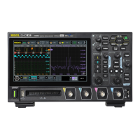
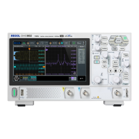
Provides visual information on the oscilloscope's front panel and overall dimensions.
Covers essential steps like adjusting legs, connecting power, and initial checks.
Explains how to connect the oscilloscope to the AC power source.
Describes how to perform a basic functional check of the instrument.
Details the procedure for compensating the oscilloscope probe for accurate measurements.
Identifies and describes the components and controls on the front panel.
Details the connectors and ports located on the rear panel of the oscilloscope.
Explains the layout and elements of the oscilloscope's graphical user interface.
Describes how to use touch gestures like tap, drag, and pinch&stretch for operation.
Explains methods for setting parameters using knobs and the touch screen.
Controls the activation status of analog channels for signal acquisition.
Details how to change the vertical sensitivity (Volts/division) for waveform display.
Explains how to shift the waveform vertically relative to the ground level.
Sets the signal coupling mode (DC, AC, GND) for each channel.
Details how to change the time scale (seconds/division) for viewing waveforms.
Explains how to move the waveform horizontally on the display.
Describes how to expand a specific portion of the waveform for detailed analysis.
Explains different modes (Normal, Average, Peak, UltraAcquire) for waveform acquisition.
Sets the rate at which the oscilloscope samples analog signals into digital data.
Determines the number of data points captured per acquisition for detailed views.
Selects the signal (analog or digital channel) used to initiate a trigger event.
Sets the voltage threshold that the signal must cross to trigger the capture.
Defines how the oscilloscope handles triggers (Auto, Normal, Single).
Selects the specific condition (e.g., Edge, Pulse, Video) for triggering.
Triggers based on the slope and level of a signal's edge.
Triggers based on the duration of a pulse meeting specific width criteria.
Triggers based on the rate of change (slope) of the signal.
Allows basic arithmetic operations (A+B, A-B, AxB, A/B) between waveforms.
Transforms time-domain signals into frequency-domain components (spectrum analysis).
Automatically adjusts settings for optimal waveform display and measurement.
Automatically measures and displays key waveform parameters.
Configures measurement source, enables functions, and selects parameters.
Measures time-related characteristics like Rise Time, Fall Time, and Period.
Measures voltage-related characteristics like Vmax, Vmin, and Vpp.
Allows selection of specific parameters from Vertical, Horizontal, and Other categories.
Enables manual measurement of X and Y values using on-screen cursors.
Provides 4-digit voltage measurements on analog channels.
Measures frequency, period, and edge events of analog channels.
Controls the activation status of individual or groups of digital channels.
Sets the voltage threshold for interpreting digital signal levels as logic 1 or 0.
Activates or deactivates the histogram analysis feature.
Displays statistical data like Sum, Peaks, Mean, and Sigma from histogram analysis.
Guides on generating Sine, Square, Ramp, DC, and Noise waveforms.
Details how to configure parameters like frequency, amplitude, and offset for sine waves.
Explains amplitude, frequency, and phase modulation for carrier waveforms.
Configures Bode plot function, sources, sweep type, and filter settings.
Activates or deactivates the Bode plot measurement capability.
Initiates or terminates the Bode plot frequency sweep and analysis.
Activates the reference waveform display and management features.
Specifies the source channel and saves waveforms as references.
Activates or deactivates the pass/fail test functionality.
Defines custom tolerance regions (masks) for pass/fail criteria.
Configures how test results (Pass/Fail events, pulses) are output.
Starts or stops the pass/fail test and displays the results.
Decodes parallel bus signals based on clock and data lines.
Configures bus parameters like width, bit assignment, and channel mapping.
Decodes RS232 serial communication data streams.
Configures Tx/Rx sources and thresholds for RS232 signal interpretation.
Decodes I2C serial bus communication, including address and data.
Decodes SPI serial communication, including clock and data lines.
Decodes LIN serial bus signals, specifying protocol version and baud rate.
Decodes CAN bus signals, setting type, sample position, and baud rate.
Allows adding multiple display windows (XY, Math) for simultaneous viewing.
Configures waveform recording parameters like interval and number of frames.
Starts and manages the process of recording waveforms.
Sets parameters for recording interval, frames, and beeper notifications.
Configures playback mode, sequence, interval, and frame selection.
Locates specified edge or pulse width trigger events in waveforms.
Allows navigating through time, search events, and segments.
Sets how long waveform traces remain visible on screen.
Adjusts grid brightness, window transparency, and cursor brightness.
Details saving waveforms, images, and setup configurations.
Describes how to capture and save the oscilloscope screen image.
Explains how to save waveform data and associated settings.
Details saving the oscilloscope's current configuration settings.
Describes how to load saved setups, waveforms, or images from storage.
Manages network configuration, IP addresses, and MAC addresses.
Automates channel examination and scaling for optimal signal display.
Performs self-calibration to ensure precise measurement accuracy.
Details connecting and controlling the instrument using a USB interface.
Describes connecting and controlling the instrument over a local area network.
Solutions for when the instrument screen is black and displays nothing.
Troubleshooting steps when no waveform appears on the screen.
Steps to resolve issues with the instrument not recognizing USB storage devices.
Guidance for when touch-enabled operations are unresponsive or not working.
Lists available options, standard accessories, and recommended accessories.
Details the default factory settings for various instrument parameters.
| Vertical Resolution | 12-bit |
|---|---|
| Resolution | 12-bit |
| Input Coupling | DC, AC, GND |
| FFT Points | Up to 1 Mpts |
| Analog Channels | 4 |
| Memory Depth | 50 Mpts per channel |
| Interfaces | USB Host, USB Device, LAN, HDMI |
| Optional Features | Decoders |
| Trigger Types | Edge, Pulse, Slope, Video, Pattern, Runt, Window, Serial |
| Math Functions | +, -, ×, /, FFT |
| Operating Temperature | 0°C to +40°C |
| Input Impedance | 1 MΩ |