Chapter 5 To Trigger the Oscilloscope RIGOL
MSO7000/DS7000 User Guide 5-37
high level.
⚫ Stop: triggers when SDA data transitions from low level to high level while SCL is
high level.
⚫ Restart: triggers when another start condition occurs before a stop condition.
⚫ MissedAck: triggers when the SDA data is high level during any acknowledgment
of SCL clock position.
⚫ Address: the trigger searches for the specified address value. When this event
occurs, the oscilloscope will trigger on the read/write bit. After this trigger
condition is selected:
➢ Press AddrBits and rotate the multifunction knob to select the desired
address bits. Then press down the knob to select it. You can also press
AddrBits continuously or enable the touch screen to select it. The available
address bits are "7 Bits", "8 Bits", and "10 Bits".
➢ Press Address, then rotate the multifunction knob or use the numeric
keypad to set the address of I2C trigger.
➢ Press More → Direction to select "Write", "Read", or "R/W".
Note: This setting is not available when AddrBits is set to "8 Bits".
⚫ Data: the trigger searches for the specified data value on the data line (SDA).
When this event occurs, the oscilloscope will trigger on the clock line (SCL)
transition edge of the last bit of data. After this trigger condition is selected:
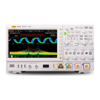
➢ Press Bit X, and set the current bit with the following two methods.
Method 1: First rotate the multifunction knob to switch to the data bit
that needs to be operated on. Then press down the knob continuously to
set the current bit. As shown in the figure below, the left is its binary format,
and the right is its corresponding Hex format.
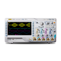
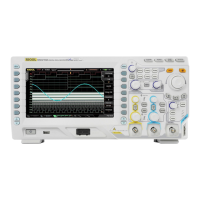
Method 2: Press Bit X or enable the touch screen to select the data bit.
Then set it with the pop-up virtual keypad. For setting methods, refer to
descriptions in "Pattern Trigger". If you modify the binary data bit, a
virtual keypad as shown in Figure 5-15 (a) is displayed. If you modify the
hex data bit, a virtual keypad as shown in Figure 5-15 (b) is displayed.
(a) Virtual Keypad for Binary Data Bit (b) Virtual Keypad for Hex Data Bit
Figure 5-15 Virtual Keypad for Data Bit Settings