GX-2009 Operator
s Manual14
Printed Circ uit Boards
The primary func tio n o f the GX-2009 s printed c irc uit bo ards is to amplify
the s ignal sent to the m fro m the fo ur gas senso rs, c o nvert the signal to a
measurement of gas c oncentration, display the gas c oncentration on the
LCD, store peak, STEL, and TWA readings, and activate the alarm circuit
if an alarm po int has been reac hed. They mo nitor battery level, battery
failure, and sensor failure. They also control the GX-2009 s time function
and various operating modes.
Alarm LED Arrays
Three red alarm LED (light emitting diode) arrays are visible through
frosted plastic lenses in the case. One is on the top, one on the left side,
one on the right side of the case. The alarm LED arrays alert you to gas,
lo w b atte ry, and failure alarms.
Buzzer & Vibrato r
A solid-state electronic buzzer is mounted inside the GX-2009 s case. The
buzzer sounds for gas alarms, failure alarms, and as an indicator during
normal use of the GX-2009 s various operating modes.
A vibrating motor inside the GX-2009 case vibrates for gas alarms and as
an indicator during normal use of the GX-2009 s various operating modes.
NiMH Batte rie s
Two NiMH (nic ke l me tal hydride) b atte ries , eac h with an integral ho ld e r,
supply 2.4 vo lts to po we r the GX-2009. The batte ries will run the unit
fo r up to 20 ho urs when no alarms have been ac tivated during that time
period. The batteries are designed to be charged while in the GX-2009
with the GX-2009 Charging Station. The batteries should not be removed
from the GX-2009 unless they need to be replaced because they will
no lo ng e r ho ld a c harge. The batte ry ic o n in the lo we r le ft c o rne r o f the
LCD shows the charge remaining in the batteries. See Recharging the
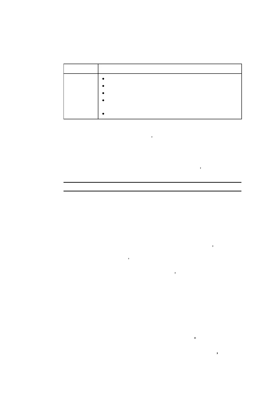
Table 2 : GX-2009 Co ntrol Buttons
Button Func tion
AIR
Turn s the LC D b a c k lig ht o n.
Performs a fresh air adjustment
Enters Calibratio n Mo de with the MODE POWER b utto n.
Enters Use r Setup Mo de with the MODE POWER
button.
Adjusts or changes displayed parameters
NOTE : The printed c irc uit bo ards c o ntain no user servic eable parts.
De s c riptio n
11
 Loading...