Do you have a question about the Rinnai Infinity 32e and is the answer not in the manual?
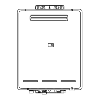
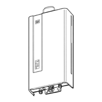
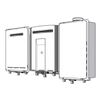
Details installation procedures for external wall mounting of the appliance.
Information and features of the standard MC-91 remote controller.
Details on deluxe remote controls for kitchen and bathroom use.
Guidelines for optimal and safe placement of remote controllers.
Instructions for wiring remote control cables to the appliance.
Steps for programming the MC-91A controller for temperature settings.
Describes the ignition sequence for the hot water unit.
Explains how temperature, flow, and volume are managed by the unit.
Details the process when the unit is turned off or stops operation.
Role of the PCB in controlling unit functions and safety devices.
How gas flow is regulated for consistent temperature output.
System for detecting and managing water flow rates.
Management of air supply for combustion based on various factors.
Components and arrangement of the combustion chamber.
Sequence and timing during normal operational combustion.
Timing and indicators for ignition failures and flame loss.
Timing and error codes for pre-purge issues.
Settings for selecting between natural gas and LPG.
Adjusting combustion modes for forced low or high output.
Information on computer programming settings via dip switches.
Dip switch configurations for specific temperature settings.
Procedures for checking the combustion fan motor and sensor.
Tests for the sparker unit and ignition plug.
Checks for the main solenoid valve's resistance and voltage.
Tests for Solenoid Valve 1 resistance and voltage.
Checks for Solenoid Valve 2 resistance and voltage.
Tests for Solenoid Valve 3 and Modulating Valve.
Procedures for testing the flame rod and its circuit.
Verifying the integrity of the earth lead connection.
Testing the thermal fuse for continuity.
Measuring resistance across the overheat switch.
Checking voltage readings for the water flow sensor.
Testing resistance and voltage for the water flow servo.
Checking resistance for the heat exchanger outlet thermistor.
Measuring resistance of the hot water outlet thermistor.
Instructions for checking and replacing the electrical fuse.
Measuring voltage at the surge protector terminals.
Testing transformer output voltages for various circuits.
Checking resistance and voltage for the bypass servo.
Verifying voltage on the remote control cable.
Measuring resistance for anti-frost heater components.
Checking continuity of the frost sensing switch.
Steps to access maintenance data and unit history.
Procedure to view the last ten recorded faults.
Instructions for removing the appliance's front panel.
Steps for safely removing the printed circuit board.
Procedure to remove water flow control components.
Steps for removing the spark ignition components.
Instructions for removing the combustion fan assembly.
Procedure to remove temperature sensing thermistors.
Steps for removing the appliance's transformers.
Procedure to remove gas inlet, solenoid valves, and flame rod.
Steps for removing the gas control assembly.
Procedure for removing the main heat exchanger unit.
Steps for removing thermal fuse and overheat switch.
| Brand | Rinnai |
|---|---|
| Model | Infinity 32e |
| Category | Water Heater |
| Language | English |