Do you have a question about the Rinnai INFINITY A-Series and is the answer not in the manual?
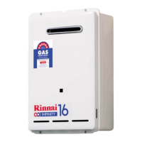
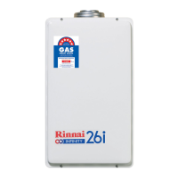
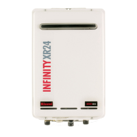
The Rinnai INFINITY EF26 and A-Series are continuous flow gas hot water heaters designed for residential applications, providing hot water on demand. These units feature electronic ignition and require an electrical power supply to operate. The EF26 model is a condensing unit, indicating higher efficiency. Both series come with built-in frost protection, which automatically activates when the internal temperature drops below 3.5 °C and deactivates when it reaches 7 °C, ensuring reliable operation in colder conditions as long as the appliance is connected to the electrical power supply.
These water heaters are designed for external mounting on an outside wall. For optimal performance and reduced hot water delivery delay, they should be located as close as practicable to the most frequently used hot water outlet(s). While they are suitable for residential use, they are not designed for spa or swimming pool heating, hydronic applications, or as gas boosters for solar installations due to temperature setting limitations. The units are factory preset to deliver water at 55 °C, with a maximum settable temperature of 65 °C. If the appliance is set to deliver water at a temperature higher than 55 °C to areas used primarily for personal hygiene, a Temperature Limiting Device (TLD) may be required to comply with AS/NZS 3500 regulations. For installations in early childhood centres, schools, or nursing homes, a TLD may be necessary even if the appliance is set to 55 °C or less.
Installation of these appliances must adhere to manufacturer's instructions and current AS/NZS 3000, AS/NZS 3500, AS/NZS 5601.1, and G12/AS1 standards. They are designed for use with Natural Gas or Universal LPG, as indicated on the appliance. The water heaters are not suitable for locations greater than 1000 m above sea level. Proper installation, commissioning, and servicing must be performed by an authorised person, specifically a licensed gasfitter in New Zealand. Improper installation, adjustment, alteration, service, or maintenance can lead to property damage, personal injury, or loss of life.
The appliance must be mounted on a vertical structure with the water and gas connections pointing downwards. An AC 230 V, 10 A earthed weatherproof power point must be provided adjacent to the appliance, clear of gas and water connections, flue exhaust, and the water pressure relief valve. The power cord is 1.5 m long. Sufficient clearances are required for maintenance and servicing, allowing access and removal of all serviceable components. The appliance should not be mounted more than 2.5 m above ground or floor level unless permanent and safe access is provided. A minimum horizontal clearance of 500 mm between the building structure and any obstruction facing the terminal is required to prevent wind from pushing flue gases back into the terminal. There must be no partial obstructions to the appliance front cover or casing, as this can cause operational failure in windy conditions.
The wall structure supporting the unit must be capable of bearing the weight of the appliance and associated pipework. Suitable fixing screws or bolts must be used for securing the unit to the wall, in accordance with AS/NZS 5601 section 6, and wooden plugs should not be used. The top bracket features a keyhole slot for easy positioning on one screw, after which additional fixings can be used. The appliance can be mounted directly against a wall or structure without needing non-combustible sheeting or an air gap, as it meets temperature hazard requirements.
Gas pipe sizing is crucial for proper appliance performance and must consider the gas input for this appliance and any other gas appliances in the premises. The gas meter and regulator must be specified for the required gas rate, using an approved sizing chart like those in AS/NZS 5601. Water pipe sizing and layout should conform to AS/NZS 3500, and all hot water pipework should be insulated to optimize performance and energy efficiency.
The appliance is intended for permanent connection to the water mains. Operational water pressure limitations must be observed, and pressure limiting valves may be required if maximum rated water supply pressures are exceeded. Minimum water supply pressures must be met to achieve rated flow. For gravity-fed or low-pressure installations, Rinnai should be contacted. Water chemistry and impurity limits are detailed in the operation guide, and most metropolitan water supplies fall within these requirements. If water quality is uncertain, the water authority should be contacted. If sludge or foreign matter is present, a suitable filter or strainer is required in the water supply to prevent damage and performance loss.
The EF26 and A-Series models feature an external thermistor for frost protection, located on the bottom right-hand side of the unit, directly beneath the cover screw. This thermistor must be exposed to outside air for correct function; insulating it will prevent the frost protection circuit from working correctly.
For the EF26 model, condensate is generated continuously at a rate of up to 5 litres per hour as a by-product of its highly efficient gas burner. This condensate is neutralised by an inbuilt neutraliser kit. The neutraliser drain pipe requires careful consideration, following guidelines similar to AS/NZS 3500 for temperature/pressure relief and expansion control valve drain lines. The black plastic shipping cap must be removed from the condensate/neutraliser drain outlet prior to operation. The drain line must not discharge onto electrical connections, earth stakes, copper pipes, concrete paths, or into a pond. The discharge point must be located to prevent nuisance, be readily discernible, and incur no risk of damage to the building. There should be no tap, valve, or other restrictions in the line, and each line must fall continuously from the valve to the approved discharge point. Drain lines should not discharge into a storage water heater safe tray. The end of the condensate line should be within specific height ranges above unpaved or paved surfaces, or discharge over a tundish or gully trap with an air gap. Non-PE plastics should not be used for drain lines due to acidic condensate, as damage caused by their use is not covered by warranty.
Condensate/neutraliser drain lines from multiple water heaters can be joined if they conform to specified requirements. In multi-storey buildings, these lines may discharge into a common stack, provided the discharge is to a tundish with a discharge line directly connected to a fixture trap and installed in connection with an adjacent soil or waste stack. The common stack discharge must be visible and not cause nuisance, and the common stack must be vented by extending the pipe upwards above roof level. Tundish drain lines must be at least DN 20 or one size larger than the largest drain line discharging into the tundish. In areas prone to freezing, drain pipes from any valve must be insulated, not exceed 300 mm in length, and discharge into a tundish through an air gap of 75-150 mm from the outlet to the rim.
Commissioning involves ensuring all gas installation parts are commissioned prior to initial use, as per AS/NZS 5601.1. The appliance operation must be tested after installation, ensuring building occupants do not have access to hot water outlets during this procedure. The Rinnai INFINITY EF26 and A-Series come with factory preset outlet temperature of 55 °C and factory preset high and low gas operating pressures. Adjustments to operating pressures should only be made if the unit is not operating correctly and all other causes for incorrect operation have been eliminated. Inlet supply pressure must be checked and set within operating parameters. If the appliance cannot be adjusted correctly, Rinnai should be contacted for assistance.
Before final connection, gas, hot, and cold water supply lines must be flushed to remove air and swarf, which can cause damage not covered by warranty. After connecting the gas line, it must be purged of air. Supply pressure must be checked with all other gas appliances operating at maximum rate, ensuring it reads between 1.13-3.0 kPa for Natural gas and 2.75-3.0 kPa for LPG. If pressure is lower, the gas supply is inadequate, and the installer is responsible for rectifying the gas meter, service regulator, and pipework. PCB settings should be checked, especially if the factory default temperature has been changed or if a sideways flue diverter is fitted. The appliance front cover must be replaced before operating and testing for gas leaks with an electronic leak detector. Finally, water flow and hot water delivery temperature must be confirmed with a thermometer. If water controllers are fitted, their operation through the complete range of functions must be tested.
The cold water inlet filter should be inspected and cleaned, especially in new installations. After testing, the customer should be informed about the function and operation of the water heater and any fitted water controllers, including information on gas, power, and water connections, frost protection, draining procedures, data plate location, and maintenance/servicing. The installer details section and commissioning checklist in the operation guide must be completed, signed, and left with the customer.
For sideways flue diverter installations, SW1 and SW3 of the DipSW must be set to the ON position (default is OFF for all switches). This increases the combustion fan speed to overcome friction losses from the diverter. The PCB interface and dip switch settings should only be changed by a licensed gasfitter. When changing these settings, care must be taken to avoid incorrect positions, and the water heater's operation, including delivered temperature, must be fully checked afterwards. The power supply must be disconnected before removing the front cover to access the PCB, as live mains voltage wiring will be exposed. New Zealand Building Code G12 requires water delivered to sanitary fixtures to be no more than 55 °C; increasing the set temperature requires suitable tempering valves for all plumbed sanitary fixtures.
The maximum number of water controllers that can be fitted is four. Only Rinnai water controllers are compatible and must not be used with solar boost water heaters or Rinnai appliances from other countries. Only one master controller (e.g., Kitchen Deluxe MC-100V or a Compact controller MC-601) can be installed. Sub-controllers, typically for bathrooms, toilets, and laundries, have a temperature limit of 50 °C for safety. A master controller must not be installed in a bathroom. Water controllers should not be installed near heat sources, outdoors without protection, in direct sunlight, against earthed metal walls, or where chemicals like benzene, alcohol, turpentine, hydrogen sulphide, ammonia, or chlorine are used. They are water resistant but excessive exposure to water can cause damage. Controllers should be installed in shaded, clean locations, out of reach of children (suggested height 1.5 m from the floor), and at least 400 mm above the highest part of a sink, basin, or bath. Cleaning should be done with a damp cloth and mild detergent.
Connecting communication cables involves using Rinnai-supplied 10 m cables. The water heater end of the cables has spade terminals. For one or two cables, these are terminated directly. For three or four cables, existing spade connectors must be cut off, and each pair re-terminated into a new spade connector (available from electrical component retailers). The power supply must be isolated before connecting cables to the water heater. The cable connector retaining screw at the unit's base is removed, the door swung open, and the cable threaded through the weather seal, allowing sufficient length for the cable clamp. Screw terminals are loosened, spade connectors connected, and then re-tightened. Polarity is not important. The cable connector is then returned to its original position, and the retaining screw replaced.
For EF26 controller communication cables, wired water controllers operate at 12 V DC supplied by the water heater. A 10 m communication cable is supplied. Water controllers connect to the PCB via a dedicated pre-wired mini-plug. Standard electrical cable connectors can be used to terminate water controller wires to those on the mini-plug. Existing spade connectors on communication cables will need to be removed. Polarity is not sensitive, but like-coloured wires should be terminated together to avoid confusion. The power supply must be switched OFF before connecting the mini-plug or water controller cables to the water heater to prevent damage to electrical components. The front cover of the appliance is removed, the mini-plug and connected water controller cables are inserted through the cable access at the base, ensuring connectors are inside for protection. The PCB (bottom right) is located, the plastic safety cover moved, and the accessory port socket (bottom front of PCB) found. The mini-plug is then plugged into the accessory port socket, which is keyed to ensure correct direction. Finally, the water controller installation proceeds, and communication cables are connected to the controllers.
| Ignition Type | Electronic Ignition |
|---|---|
| Type | Tankless |
| Energy Source | Natural Gas or Propane |
| Energy Efficiency | High Efficiency |
| Venting | Concentric or twin pipe system |
| Control Type | Digital |
| Safety Features | Freeze protection, overheat protection |