Do you have a question about the Rinnai INFINITY A24 and is the answer not in the manual?
Improper installation, adjustment, alteration, service, and maintenance can cause property damage, personal injury or loss of life.
Defines the intended applications and limitations for Rinnai INFINITY water heaters.
Provides key technical data, including thermal efficiency, capacity, input/output, and weight.
Lists built-in safety features such as flame failure, boil-dry protection, and overheat protection.
Specifies the required Natural Gas (NG) and LPG line pressures for proper operation.
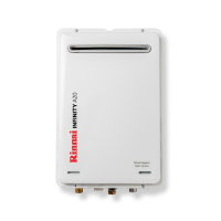
Details connection points and dimensions for A-Series models.
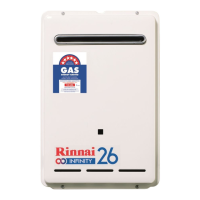
Details connection points and dimensions for the EF26 model.
Highlights essential connection requirements like isolation valves and unions for safe installation.
Specifies minimum clearances required around the flue terminal to prevent wind interference.
Guidance on wall mounting, fixing methods, and structural support requirements.
Details on gas and water pipe sizing considerations for optimal performance.
Information on water pressure limitations, chemistry, and the need for filters.
Explains the automatic frost protection feature and its operating temperatures.
Locates and describes the function of the external thermistor for frost protection.
Details temperature limitations for hygiene areas and the need for Temperature Limiting Devices (TLDs).
Notes on controller compatibility, servicing, and Rinnai-specific requirements.
Defines the role of the master controller and its placement restrictions.
Explains how many controllers can be fitted and their types (Compact, Kitchen Deluxe).
Provides guidelines on suitable and unsuitable locations for water controllers.
Guidance on the condensate drain pipe, including material suitability and discharge points.
Details on the installation of the condensate drain line, including discharge requirements and air gaps.
Procedures for joining condensate/neutraliser drain lines from multiple heaters.
Requirements for discharging condensate into a common stack in multi-storey buildings.
Specifications for drain lines connected to tundishes.
Recommendations for insulating drain pipes in freezing-prone areas.
A step-by-step guide to testing and verifying the appliance after installation.
Instructions for inspecting and cleaning the cold water inlet filter.
Guidance on explaining the appliance's operation and maintenance to the customer.
Details on navigating the PCB menu, altering values, and saving settings.
Information on a specific error code related to the neutraliser and how to cancel it.
How to terminate single communication cables for A-Series controllers.
How to terminate paired communication cables for A-Series controllers.
Steps for connecting one or two communication cables to the water heater.
Steps for connecting three or four communication cables to the water heater.
Guidance on connecting controller cables to the PCB mini-plug safely.
Steps for routing and connecting controller cables to the appliance's PCB.
| Energy Rating | ENERGY STAR Certified |
|---|---|
| Maximum BTU Input | 199, 000 BTU/hr |
| Minimum BTU Input | 15, 000 BTU/hr |
| Energy Factor | 0.82 |
| Maximum Water Pressure | 150 psi |
| Ignition Type | Electronic Ignition |
| Gas Type | Natural Gas |
| Temperature Range | 98°F - 140°F |
| Water Connection | 3/4 inch |
| Electrical Requirements | 120V, 60Hz |
| Minimum Water Pressure | 15 psi |