Rinnai INFINITY EF26 and A-Series installation guide 01-20 | 5
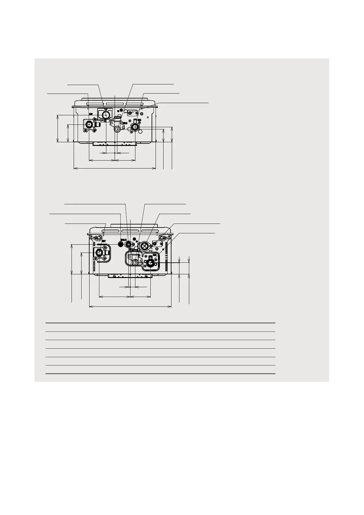
Connections and ttings
Cable access
Cold water inlet
Gas connection
Power supply cable
Hot water outlet
62 (gas)
53 (cold)
110.4 (cable)
72 (hot)
36
10
105 83
335.6
Hot Cold Gas Condensate
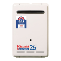
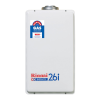
A16 external REU-A1620WG-ZK R½ (15 mm) R½ (15 mm) R¾ (20 mm) N/A
A20 external REU-A2024WG-ZK R¾ (20 mm) R¾ (20 mm) R¾ (20 mm) N/A
A24 external REU-A2426WG-ZK R¾ (20 mm) R¾ (20 mm) R¾ (20 mm) N/A
A26 external REU-A2626WG-ZK R¾ (20 mm) R¾ (20 mm) R¾ (20 mm) N/A
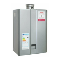
EF26 external REU-E2626W-ZK R¾ (20 mm) R¾ (20 mm) R¾ (20 mm) R½ (15 mm)
From bottom of unit:
• Hot 41 mm (A16 39 mm)
• Cable 29 mm
• Gas 40 mm
• Cold 50 mm
From bottom of unit:
• Hot 41 mm
• Cable 26 mm
• Gas 38 mm
• Cold 50 mm
Neutraliser drain outlet
Neutraliser tank drain valve
Hot water outlet
Cold water inlet
Cable access
Power supply cable
Gas connection
47.8 (cold)
46.4 (gas)
122 (drain)
88.1 (hot)
335.6
126.8
83
7
20
Service connection points
An approved full ow isolation valve and disconnection union MUST BE tted to the cold water
inlet. A non-return valve is not required unless stipulated by local regulations.
Isolation valves MUST NOT be tted directly the appliance.
It may be necessary to t a temperature limiting device for delivery to areas used primarily for the
purposes of personal hygiene, refer page on ‘Water delivery temperature’ for more information.
Purge gas and cold water supply lines to remove air and swarf before nal connection. Swarf in the
gas or water supplies may cause damage, a common problem, which is not covered by warranty.
A-Series
EF26