18 | Rinnai INFINITY EF26 and A-Series installation guide 01-20
A-Series controller communication cables
Wired water controllers operate at an extra low voltage (12 V DC) which is supplied from the water
heater, a 10 m long communication cable is supplied for connection to the water heater. Only
Rinnai supplied communication cables may be used.
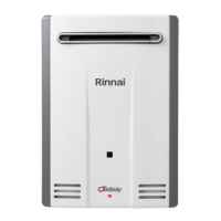
The water heater end of the cables is tted with spade terminals. Only two pairs of cables (four
spade connectors in total) may be terminated. When attaching three or four cables it is necessary
to join the cable terminators as shown below.
For each pair cut o the existing spade connectors and re-terminate each pair into a new spade
connector (A). Spade connectors are available from your local electrical component retailer
A
Single cables can be used
when terminating up to two
communication cables.
Paired cables are to be used
when terminating three or four
communication cables.
Connecting one or two communication cables
Follow steps one through ve below to terminate the cables to the water heater.
Connecting three or four communication cables
To connect three or four cables, separate all the cables to be tted into pairs.
A
A
A
When
terminating
three cables
When
terminating four
cables
Follow steps one through ve below to terminate the joined cable pairs to the water heater.
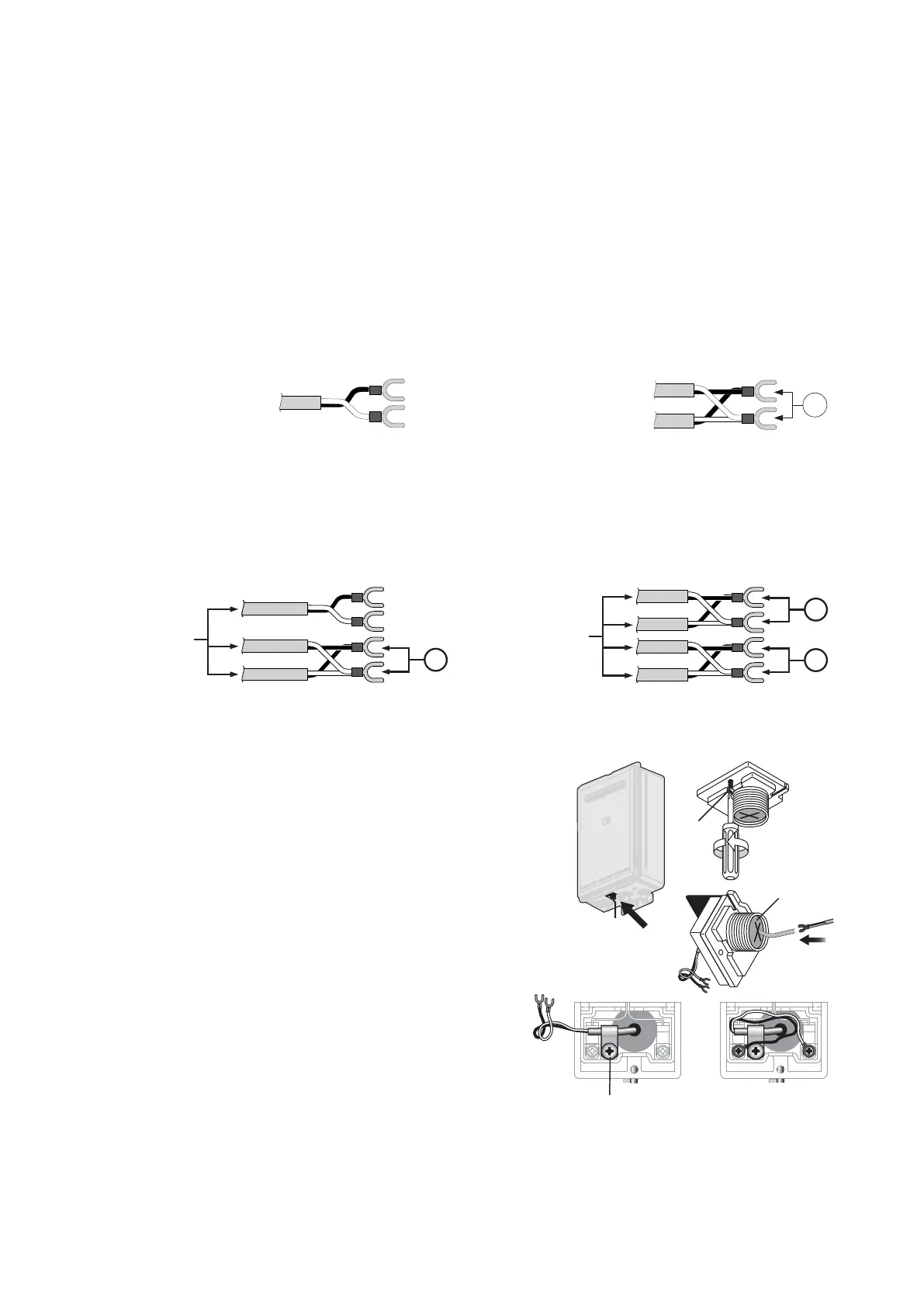
1. Isolate the power supply by switching the power point
o and removing the power plug of the water heater
from the electric power socket.
2. Removing the retaining screw of the cable connector
at the base of the unit.
3. Swing the cable connector door open and thread the
cable through the weather seal of the cable access
hole, allowing sucient cable length so that the sheath
of the cable can be secured with the cable clamp
supplied with the transceiver.
4. Loosen the screw terminals and connect the cable
spade connectors to these terminals and re-tighten.
Polarity is not important, either wire colour can be
connected to either terminal.
5. Return the cable connector to the original position,
taking care not to damage the cable wires in the
process, and replace the retaining screw.
Retaining
screw
Cable access
Cable clamp