KBP Series Manual 39
Isolaon Valves and Pressure Relief Valve
(PRV)
The isolaon valves provide the ability to isolate the
water heater from the structure’s plumbing and allow
quick access to ush the heat exchanger. Check with
local codes to determine if a pressure and
temperature relief valve is required. The included
valves meet American Naonal Standard (ANSI
Z21.10.3) / Canadian Standard (CSA 4.3) and are
ANSI/NSF 61 approved for potable water.
1. Wrap the ends of the threaded water inlet and
outlet on the tankless water heater, as well as
the threaded end of the approved pressure relief
valve with a minimum of 5 wraps of Teon®
tape.
2. Install the pressure relief valve to the 3/4”
threaded port on the HOT (RED) water service
valve (will be adjacent to or above the cut o,
never below). See Pressure Relief Valve Secon
for proper installaon requirements.
3. Loosen the 3/4” union nut on the HOT water
valve and connect to the HOT water outlet on
the tankless water heater. If nut is removed,
ensure that you realign the tailpiece accurately
to the valve, and that the black washer and/or
gasket is properly posioned.
4. Align the direcon of the HOT water drain to the
desired posion.
5. Tighten the union assembly to the HOT water
valve. over torque.
6. Repeat steps 3-5 for the COLD water valve.
(BLUE valve) for connecon to the COLD water
inlet on the tankless water heater.
7. Connect the INLET on the COLD water valve to
the MAIN SOURCE of the water supply.
8. Connect the OUTLET on the HOT water valve to
the HOT WATER plumbing system.
9. Ensure that both drain valves are in the
closed/“OFF” posion.
The PRV must be connected to the 3/4” threaded port
on the HOT (RED) water service valve (will be adjacent
to or above the shut o, never below). Installaon
must maintain a ¾” port size with no shut o valve or
line restricon in-between the appliance and the PRV.
The discharge line from the PRV should pitch
downward and terminate 6” above drains where
discharge will be clearly visible. The discharge end of
the line shall be plain (unthreaded) and a minimum of
¾” in diameter. The discharge line material must be
suitable for water at least 180° Fahrenheit. No valve
of any type may be installed in the discharge line of
the pressure relief valve.
For proper care of this approved pressure relief valve,
it is recommended that the valve be manually
operated once a year. In doing so, it will be necessary
to take precauons with regard to the discharge of
potenally scalding hot water under pressure. Ensure
discharge water has a safe place to ow. Contact
may cause property damage and/or bodily harm.
Please note that the included PRV meets the rang
requirements for use with the tankless water heater.
Should a replacement valve be needed it must be
rated for up to 150 psi and at least the maximum
BTU/hr of the appliance.
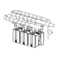
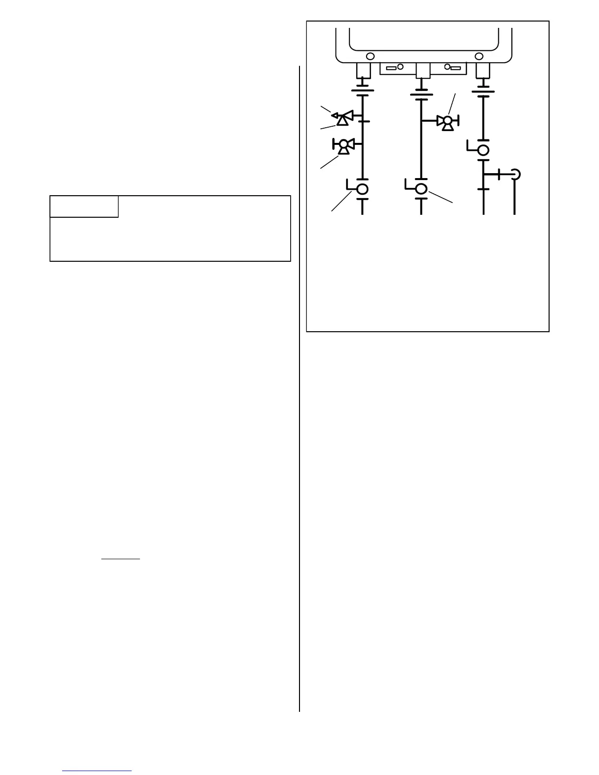
Pressure Relief Valve (PRV)
PRV Discharge Outlet
Hot Drain Valve
Cold Drain Valve
Hot Ball Valve
Cold Ball Valve
When unscrewing the UNION FITTING, Be careful not
to lose any washers and/or gaskets that may be
present.

 Loading...