PUB. NO. FASTRAXC FEBRUARY 2008 11
FASTRAX
™
1. It is the responsibility of the buyer to provide electrical
service up to the control box with proper branch service
protection and an approved means of disconnect.
2. All control boxes should be mounted on the warm side
regardless of door mount side.
3. The incoming power terminals in the control box will not
accommodate wires larger than 12AWG. 20 or 30 Amp
service may be required for cable runs longer than 300’.
4. The control box is provided with class CC protective
fusing for the incoming power.
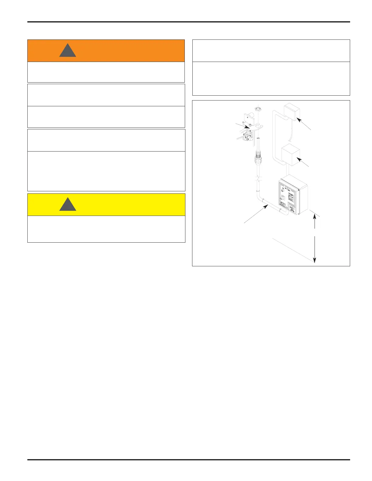
5. Mount the control box on a wall adjacent to the door at
approximately 54" above the floor level, Figure 20.
6. Run the control cable from the conduit mounting bracket
to the conduit fitting in the bottom of the control box.
NOTE: Make sure to route the cable so that it does not
interfere with the installation of the motor shroud.
If the flexible conduit is too long for the
installation, cut the protective outer casing and
leave 16" to 20" of wires. Do not connect the
conduit to the fitting on the control box until
correct conduit and wire length is achieved.
Local electrical codes may require the use of rigid
conduit, rather than flexible conduit. If required,
remove the control cables from the furnished
flexible conduit, install the rigid conduit in its place
and rewire. Make sure to remove and replace the
conduit connector in the bottom of the control box.
7. Drill a hole for the power supply cable (by others) in the
bottom of the control box using the proper connection to
maintain the NEMA rating on the enclosure. Incoming
3-phase power must connect into fuse holder terminals
F1, F2, and F3. Ground must attach to the green/yellow
terminal. All holes drilled through the control box must be
through the bottom of the box, Figure 21.
8. Route all field installed wires so that separation is
maintained between line voltage wires and low voltage
class II wiring. Electrical prints included in the control box
supersede any prints included in this owners manual on
Pages 28-35. Always check parts or control box for prints.
9. Separate 110VAC is required for the power of the
Thermal Air Seal blower, E-Vac or Virtual Vision junction
box.
10. Option provided for Step-Down Transformer to power the
Thermal Air Seal junction box.
ELECTRICAL INSTALLATION
When working with electrical or electronic controls, make sure
that the power source has been locked out and tagged according
to OSHA regulations and approved local electrical codes.
WARNING!!!
!
A qualified electrician should install the wiring in accordance with
local and national electrical codes. Use lockout and tagout
procedures to avoid injury.
IMPORTANT!!!
When drilling holes in the box, DO NOT turn control box upside
down or go too deeply into the box. Damage or debris may fall
into electrical components causing failure or severe equipment
damage.
CAUTION !!!
!
To reduce risk of injury or death, an earth ground connection
MUST BE made to the green/yellow control box ground terminal.
If metal conduit is used as the ground connector, an N.E.C.
approved ground bushing and green/yellow wire MUST BE
properly attached to the conduit for connection to the ground
terminal.
IMPORTANT!!!
In freezer and cooler applications where a conduit passes from a
warm to cold temperature zone, the conduit must be plugged with
epoxy. This will help prevent condensation from forming in the
conduit. For more information, see Section 300-7a of the National
Electric Code.
IMPORTANT!!!
FIGURE 20 - CONTROL BOX
54”
Conduit Bracket
Control Box Cable
Step Down
Transformer
Thermal Air
Seal, E-Vac or
Virtual Vision
Junction Box
 Loading...