PUB. NO. FASTRAXC FEBRUARY 2008 3
FASTRAX
™
It is important to verify the following basic
information before starting with the installation.
TO PREVENT DAMAGE TO CONTENTS, STORE DRY
BETWEEN 40° AND 80° F.
1. Make sure that you are working at the correct location and
that you have any required work permits.
2. Inspect the site to make sure that there are no overhead
obstructions (sprinkler pipes, HVAC systems, electrical
supply lines, etc.) that might interfere with the installation.
3. Detour material handling equipment during the installation.
4. Make sure that the electrician is ready to bring the correct
electrical power supply to the door control box.
5. Make sure that the electrical power can be shut off
without interfering with other plant operations.
6. Move the door crate as close to the opening as possible.
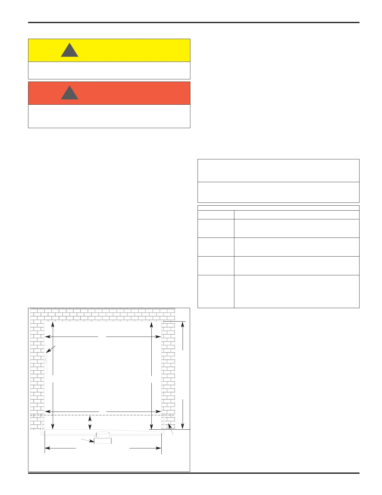
7. Measure the overall width of the door opening near the
floor and the header (Dimensions A and B), and the
height of the door opening at the left and right-hand sides
(Dimensions C and D), Figure 1.
8. Using a 6’ carpenter’s level, verify that the door jambs and
header are plumb and perpendicular.
9. These dimensions should be within ± 1/2" of the
dimensions listed on the Serial Number label. If the
measurements do not agree, STOP!
Contact your RITE-HITE DOORS, INC. representative.
10. Using a hydro level, determine if the floor is level,
Figure 1. If the floor is not level to within 1/8", mark the
wall where the level point is indicated. The measurement
between the level mark and the floor is the amount of
shimming that needs to be done under the track that will
be located on the “Low Side” (greatest measurement) of
the door opening.
11. Install optional equipment after verifying door operation.
NOTE: Electrical prints included in the parts or control
box, supersede any prints included in this owners
manual on Pages 28-35. Always check for
electrical prints.
OPTIONAL POLY LUMBER INSTALLATION
1. If your door is equipped with optional poly lumber, refer to
Figures 2, 2A, 3B or 3C.
2. For standard FasTrax door, place outside of vertical poly
lumber pieces at 1/2 O.D.W. + 7 1/2” from centerline of
opening. (Ordered Door Width), Figures 2, 2A or 3B.
3. For FasTrax FR door, place outside of vertical poly lumber
pieces at 1/2 O.D.W. + 8 3/4” from centerline of opening,
Figures 2 & 3C.
4. For FasTrax, place top of horizontal piece at O.D.H.
+ 7 1/2” and O.D.H. + 10”, Figures 2, 2A or 3B. for
FasTrax FR (FReezer) door. (Ordered Door Height),
Figures 2 & 3C.
5. Install lower track upper mount pieces per Figure 2.
6. Caulk behind poly lumber pieces to prevent air transfer.
POLY LUMBER INSTALLATION
Make sure to barricade the door opening on both sides to prevent
unauthorized use until the door has been completely installed.
CAUTION !!!
!
When working with electrical or electronic controls, make sure
that the power source has been locked out and tagged according
to OSHA regulations and approved local electrical codes.
DANGER !!!
!
LISTING OF MEASUREMENTS AND
MARKINGS REQUIRED
1. Door width at bottom.
2. Door width at top.
3. Door height left.
4. Door height right.
5. Mark left wall where water is level.
6. Mark right wall where water is level.
C
Hydro-Level
AA
BB
48”
Level
Ordered Door Height
Ordered Door Width
D
High Side
Low Side ± 1/8"
FIGURE 1 - POLY LUMBER
Surface,
MUST be
Flat, Smooth
and Collinear
With
Opposite
Side
It is imperative that the tracks be mounted at the proper width.
If mounted too wide, excess wear is placed on the drive spheres.
If too narrow, the curtain may appear wavy or crease in the center.
IMPORTANT!!!
RECOMMENDED MOUNTING FASTENERS
Wall Fastener
Wood Lower Track - 3/8" thru-bolt at top, middle, and bottom.
5/16" x 1-1/2" lag screws at all other fastener positions.
Upper Track - 5/16" x 1-1/2" lag screws at all positions.
Wood / Steel Lower Track - 3/8" thru-bolt at top, middle, and bottom.
5/16" x 1-1/2" lag screws at all other fastener positions.
Upper Track - 5/16" x 1-1/2" lag screws at all positions.
Wood / Masonry Lower Track - 3/8" thru-bolt or 3/8" masonry anchor at
top, middle, and bottom. 5/16" x 1-1/2" lag screws at all
other fastener positions.
Steel 1. 3/8" thru-bolt.
2. 3/8" drill and tap (material must be 5/16" min.).
3. 3/8" drive self tap/drill screws (1/4" – 14).
4. Weld, lower track is aluminum, only weld if steel
jamb option is included or provided by others.