8 PUB. NO. FASTRAXC FEBRUARY 2008
FASTRAX
™
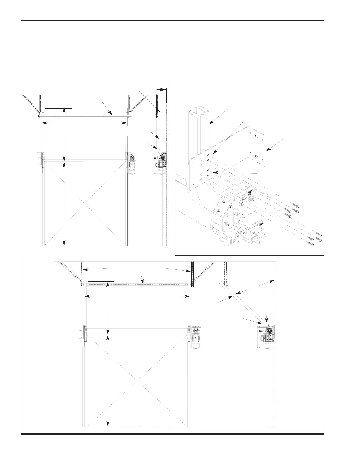
VERTICAL / 45° TILT UPPER TRACK INSTALLATION
1. The proper radius should already be assembled to the
lower track.
2. Locate the 2 pieces of upper track and the supplied wall
mount brackets.
3. Slide end of upper track into the lower track radius, level,
plumb, and hold in place, Figure 15.
4. Place mounting bracket in position and mark holes to be
drilled in wall, Figures 13 & 14.
5. Fasten mounting brackets to the wall.
6. Fasten mounting brackets to upper track.
7. Pilot holes (.201Ø x 1 1/4” deep) MUST be predrilled into
lower track radius. Make sure drill is perpendicular and
level, DO NOT drill into curtain groove.
8. Repeat for opposite track.
FIGURE 13 - VERTICAL LIFT
Upper Track Wall Mount Bracket
Track Splice
Bracket
O.D.H. + 19”
O.D.H.
Radius
11 1/2”
FIGURE 14 - 45° TILT
FasTrax = O.D.W. + 5 1/2” [+ 1/8"/-0]
FasTrax FR = O.D.W. + 14” [+ 1/8"/-0]
Upper Track Bracing
Track Splice Bracket
O.D.H. + 19”
O.D.H.
Radius
O.D.H. + 3”
45°
FIGURE 15 - VERTICAL
Vertical Lift Track
Vertical Track
Wall Mount &
Splice Bracket
Self/Tap Drill
Screws
Drill .201Ø Pilot Hole
1 1/4” Deep for Lag
Screws
FasTrax = O.D.W. + 5 1/2” [+ 1/8"/-0]
FasTrax FR = O.D.W. + 14” [+ 1/8"/-0]
Spreader Bar