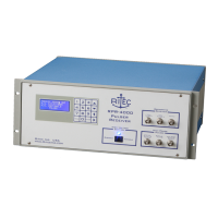
RPR-4000
Operations manual
REV 8-21 17
RF gate monitor / Amp gate monitor / Synth monitor
These are monitor signals that are usually only used for troubleshooting and system
verification.
CW input
Only used in Amplifier Mode – input connector for the RF signal to be amplified.
Amp gate input
Only used in Amplifier mode – input connector for the TTL gate signal to gate the power
amplifier.
Trigger input / Trigger Output
Trigger output acts as a trigger source when trigger mode is set to INT. Trigger input is
active when trigger source is set to EXT.
Remote Comm. RS-232
Female DB-9 connector for the RS-232 interface. For information on using the remote
interface please see “Section 3: Remote Programming.”
Power supply output
A +12V and -12V power supply, each rated for 100 mA, has been brought out for
powering accessories such as pre-amplifiers, etc.
High voltage power supply fuse holder
This holds the fuse for the high voltage power supply. For information on changing the
fuse, please see “Section 4: Trouble shooting and maintenance.”
 Loading...