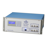
RPR-4000
Operations manual
REV 8-21 18
Getting Started
This information is intended to help first time users get started. This section contains
procedures for verifying that the system is functioning correctly and for getting
measurements set up. Operation of the RPR-4000 requires parameters, such as the
receiver gain, pulse width, pulse frequency, etc. to be optimized for a particular
measurement.
Verifying system functionality
Two short procedures are provided that verifies that both the pulser and receiver are
functioning correctly. It does not provide any information on calibration of either
module; for information on calibrating the instrument, please contact RITEC or your
RITEC representative.
Verifying pulser functionality
1. Connect coax cable from “High Power RF Pulse Output” to an appropriate high
power load. Acceptable loads include:
-A low VSWR high power 50 Ω coaxial attenuator rated for at least 500 W CW.
-An RT-150, which is a 150 Ω high power termination that is often supplied with
the RPR-4000 system.
2. Connect a coaxial cable from “Trigger Out” on the rear panel of the RPR-4000 to
the external trigger input on the oscilloscope.
3. Connect a coaxial cable “RF Pulse Monitor” to a 50 Ω terminated input on the
oscilloscope. Set the channel’s vertical sensitivity to 1 V per division. Because
the monitor output is down 40 dB (100:1 ratio), this vertical sensitivity then
corresponds to 100 V per division.
4. Set the time oscilloscope horizontal scale for 1 μs per division. Verify that the
oscilloscope is triggering on the trigger signal from the RPR-4000.
5. Using the keypad on the front panel set the various operating parameters as
follows:
Page 1 – Pulser settings 1/2
Frequency: 1 MHz
Pulse Width: 5 cycles
Page 2 – Pulser settings 2/2
Tracking: Y
Control: 10
 Loading...