RPR-4000
Operations manual
REV 8-21 30
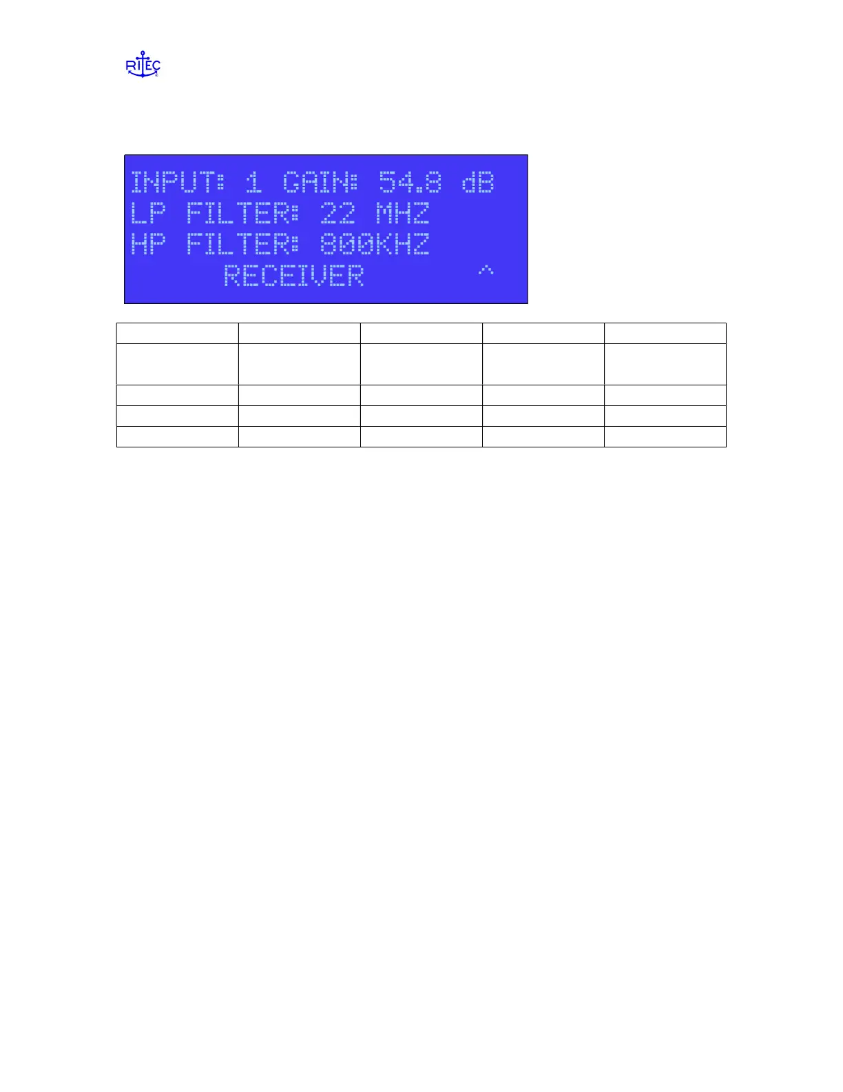
Page 3 – Receiver settings
Label Parameter Data range Units Data type
INPUT Receiver input
channel
1,2, or A alpha
GAIN Receiver gain 20.0 to 99.9 dB numeric
LP FILTER Low pass filter 8 values alpha
HP FILTER High pass filter 8 values alpha
Receiver input channel INPUT
Input must be selected using the UP ARROW key. When Input 1 or 2 is selected the
corresponding gain will also be displayed. When Input A is selected the GAIN data field
will go blank. In this mode Inputs 1 and 2 will be alternately selected based on the
current repetition rate (RR) and will use the current gain settings. The GAIN data field is
not accessible when A is selected.
Receiver gain GAIN
Gain setting range is 20 to 99.9 dB. Gain is set in increments of 0.4 dB starting at 20 dB.
If the selected setting entered is not a 0.4dB increment the unit will round down to the
closest 0.4 dB setting which will then be displayed.
NOTE: Channels 1 and 2 can be set to have different gains.
Low/High Pass Filter LP / HP FILTER
These are also alpha data fields. Eight settings are available for both the high and low
filter settings and are assigned at the factory based on customer requirements. Both high
and low filter settings apply to both channels 1 and 2 therefore filter settings for inputs 1
and 2 will always be the same.
NOTE: When making adjustments to the filter, you must press ENTER in
order for the new filter to be switched in. It is common, when setting up the
instrument and viewing received signal on an oscilloscope, to view the affect of changing
filters on the viewed signals. You must press ENTER after changing the filter to see any
affect.
 Loading...