Rittal Liquid Cooling Package 23
6 Installation
6
valve should be provided to extract air from the con-
nection pipes and/or any part of the cooling system
that remains unfilled.
4. Refrigerant lines must be protected or covered to
prevent damage.
5. Flexible connecting parts such as connection lines
between indoor and outdoor devices that could be-
come displaced during regular work operations
must be protected against mechanical damage.
6. The maximum distance between the brackets of the
copper pipes is 2 m.
Laying the pipework
1. The equivalent length of the overall line between the
LCP DX and the condenser must not exceed a max-
imum of 45 m. To calculate the equivalent length, in
addition to the actual length of the pipeline, the
equivalent length of curves and valves should be
taken into account.
2. The number of curves should be kept to a bare min-
imum so as to avoid pressure losses. Where curves
are unavoidable, the radius chosen should be as
large as possible.
3. When planning the piping layout ensure that the
lines between the LCP DX and the condenser are as
short as possible. Only allow for exceptions to save
unnecessary bends.
4. If at all possible, do not conduct refrigerant lines
through rooms which are ouccpied by people, such
as offices and meeting rooms.
5. The gas line must be laid with an incline of 1% in the
direction of flow of the coolant.
6. A distance of at least 20 mm between the gas and
the liquid line should be observed. If this is not pos-
sible, both lines should be adequately insulated.
7. When laying out the refrigerant lines, be sure no sag
is created in which oil may collect; install oil traps if
necessary.
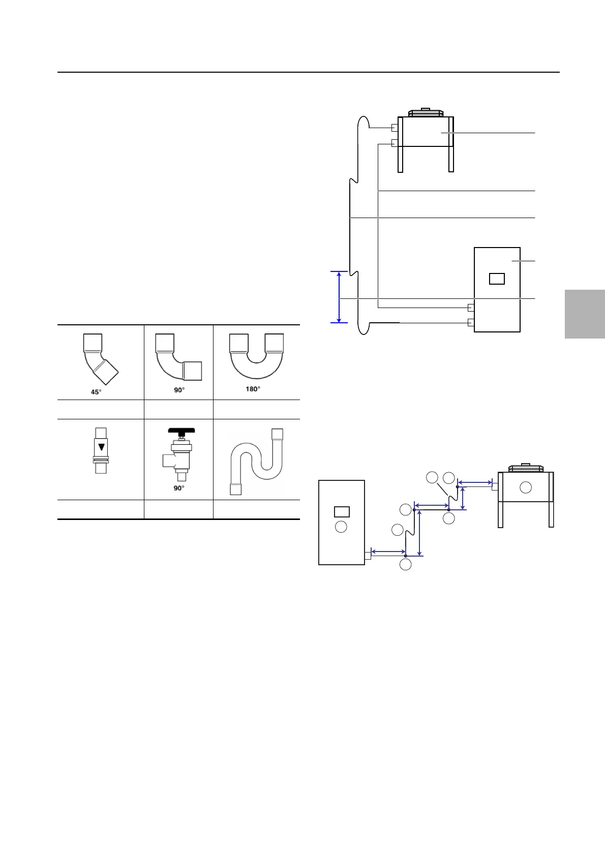
8. Provide one elevation arc at least every 6 m of line
length.
Fig. 23: Oil elevation arc
Key
1 External condenser
2Liquid line
3 Hot gas line
4LCPDX
5 Spacing max. 6 m
Sample calculation of overall length
Calculating the overall length of the pipeline is explained
using the following diagram.
Fig. 24: Simplified representation of connection lines
Key
1 Curves 90° (4 x)
2 Oil elevation arc (2 x)
3 External condenser
4LCPDX
The overall length of the pipeline is comprised of the
actual length of the pipeline and the equivalent length
of the installed moulded parts. The equivalent length
makes allowance for pressure loss from moulded parts
such as curves and valves. The overall length calculated
in this way must not exceed the maximum admissible
length of the pipeline.
The actual length of the pipeline is derived by adding to-
gether the line sections (see fig. 24):
3m + 2m + 3m + 4m + 3m = 15m
0.25 m 0.5 m 0.75 m
1.90 m 2.10 m 3.0 m
Tab. 5: Equivalent length for external diameter 12 mm
2
1
3
4
5
1
1
1
2
1
2
1
1
1
4
1
3
1
1
1
1
4 m
3 m
3 m
3 m
2 m
 Loading...