5. UPS Working Principle
5.1. UPS System Block Diagram
Fig 5.1
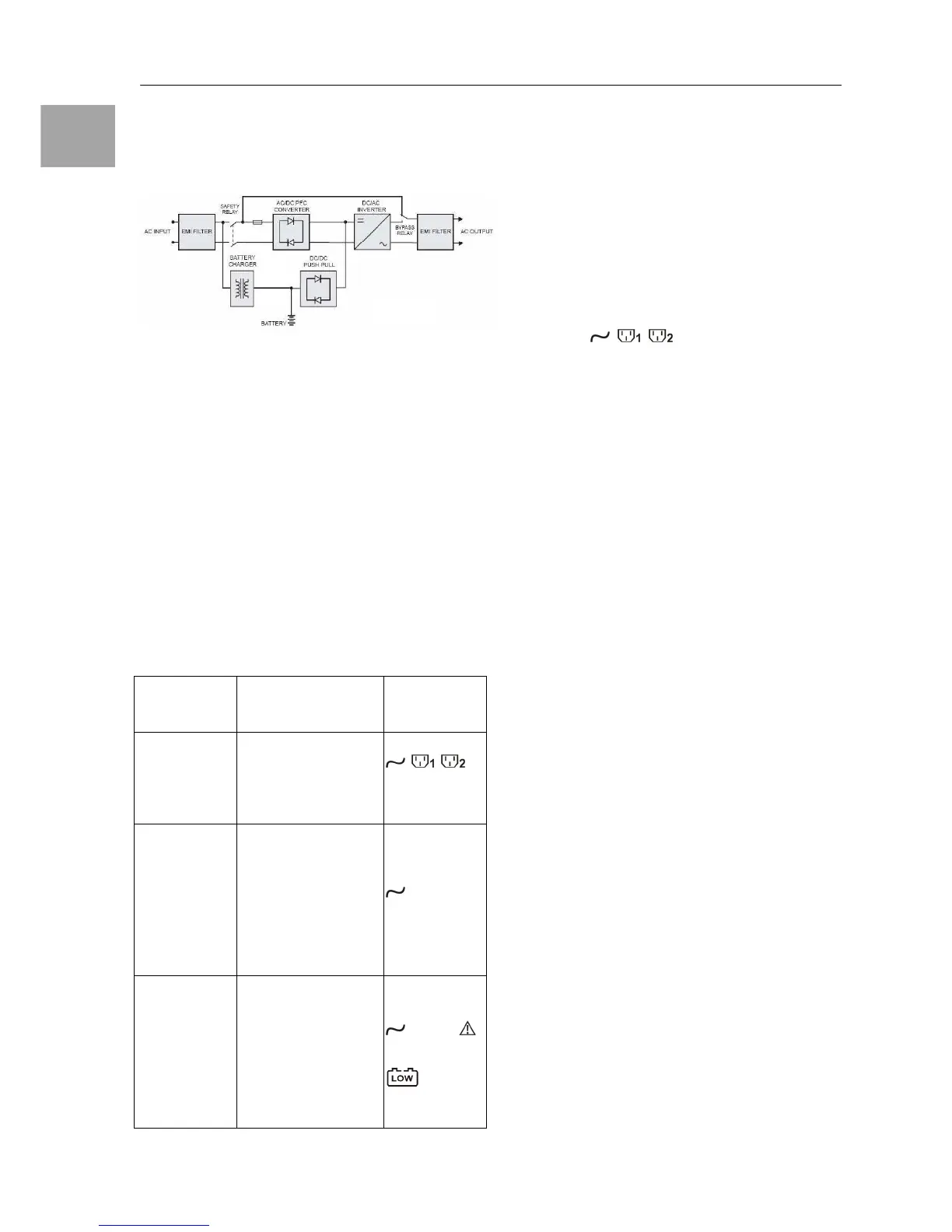
Figure 5.1 above illustrates the True On-Line
Double Conversion architecture of the UPS
system. The major modules consist of:
1. An AC to DC power converter (Rectifier) with
PFC control circuit
2. A DC to AC power high frequency inverter
3. An Intelligent Battery Charger
4. A bank of stationary maintenance-free
batteries
5. A DC to DC push/pull converter control
circuit
6. A Static Bypass Loop
7. Input & Output EMI Filter
The table below provide a summery guide to
the UPS operating modes against the Utility AC
Power Source conditions.
Utility
Conditions
UPS Operating
Modes
LEDs
Display
indications
.
Paragraph 5.2 ~ 5.7 below provide detailed de-
scriptions of the UPS operating principle.
5.2. When Mains is Available
When Mains is available, the AC source is rec-
tified to DC, partially fed into the charger to
charge battery and partially fed into inverter.
The inverter revert the DC to a cleaned and
pure AC to supply energy to the load con-
nected. The , , LED’s illuminated.