drawing M
drawing N
drawing O
4.4.4. UPS Default Data and Special
Function Execution
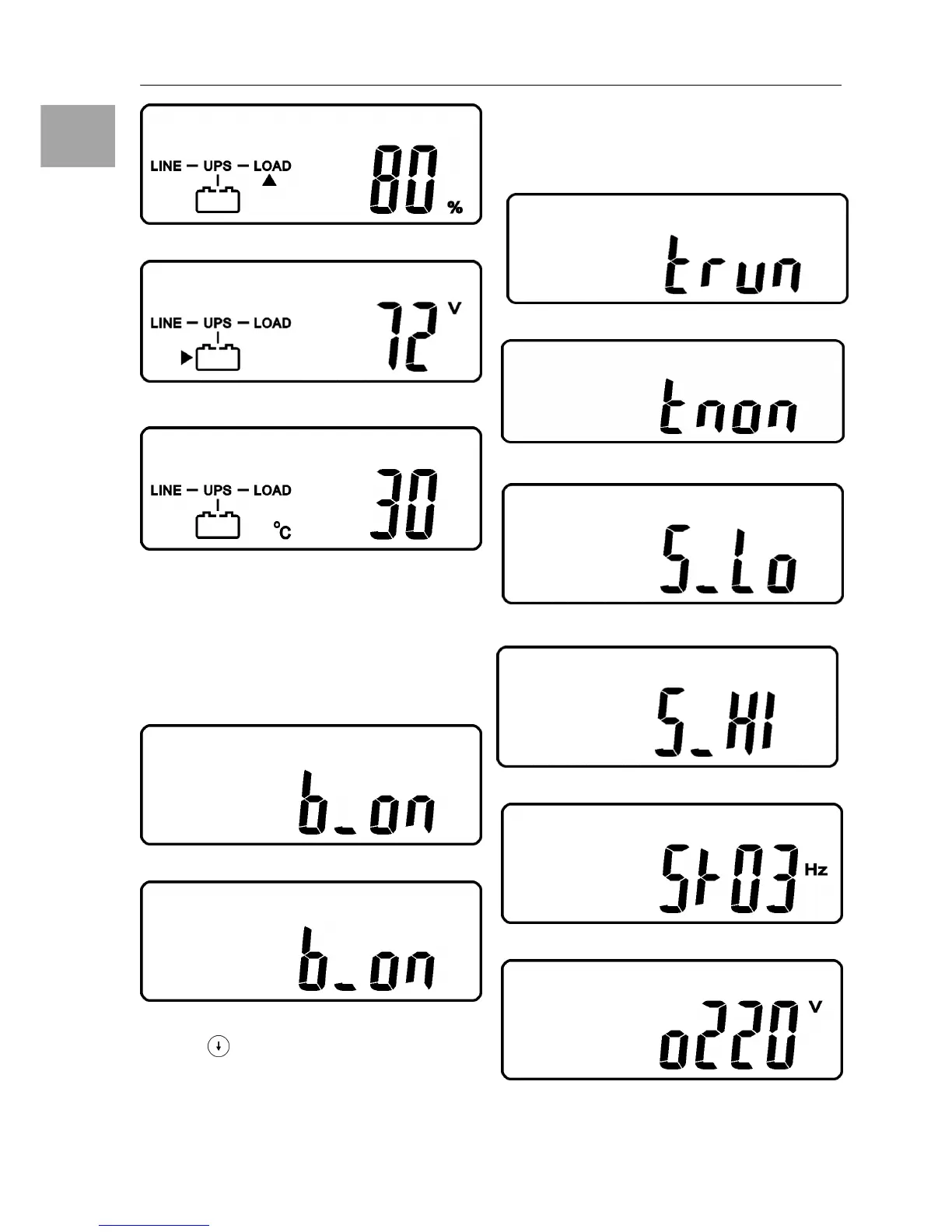
1. After UPS is turned on successfully, use
key 9 (Chapter 3.1) pad to change the LCD
Display screen to drawing P1.
drawing P1
drawing P2
2. Press key pad to scroll down the LCD
screen, then check the UPS settings. The
LCD display will show in sequence: drawing
P1(buzzer)
drawing Q1(self test)drawing
R1(Bypass Voltage)drawing S(Output Fre-
quency Synchronized Window)
drawing T
(Inverter Output Voltage)drawing U1(UPS
Operation Mode)drawing V(Output Voltage
Fine Tuning).
drawing Q1
drawing Q2
drawing R1
drawing R2
drawing S
drawing T