4
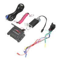
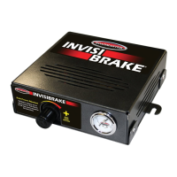
11. Plug the 12 volt cord into the power outlet. Secure cord using the cord lock as shown in figure 2a through
2c. IMPORTANT! You must push the cord lock forward into the cigarette lighter to properly secure the
plug. Failure to use the cord lock may allow the plug to vibrate loose, causing intermittent power supply
and the Receiver lights to flash. If your Receiver lights flash for no apparent reason, verify that the 12 volt
plug is properly secured with the cord lock.
12. At this time, the red light on the 12 volt plug should illuminate. If not, you have no power. Some cars have
no power to the cigarette lighter connection unless the ignition is on. In that case, use part number 9332
(not included) to add a 12 volt outlet.
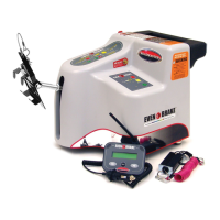
13. Once you have power, the compressor should run briefly.
Make sure the brake pedal is not being depressed as this will apply the brakes
causing severe brake damage or even a brake fire.
THIS WILL NOT BE COVERED UNDER WARRANTY
CAUTION:
!
CHECK 12 VOLT OUTLET BEFORE PLUGGING IN THE UNIT. If you use any
12 volt socket other than your car’s factory wired outlet, make certain that the
socket has been wired correctly. The bottom center of the 12 volt outlet is
always positive while the round outer shell is always negative. If the positive and negative wires are
reversed, you will blow the 20 amp fuse in the end of the 12 volt power cord.
CAUTION:
!
Installation continued
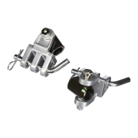
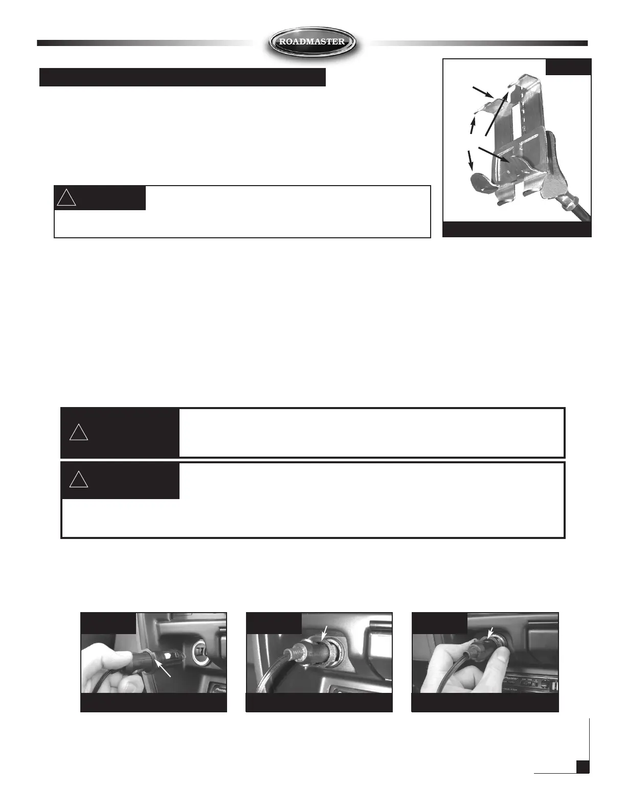
6. Place pedal clamp so that the bottom tabs are hooked on brake pedal as
shown in Figure 1a. Now compress pedal clamp at top and bottom and
ratchet it down until fully secure on brake pedal as shown in Figure 1b.
Use pliers to bend the five tabs in Figure 2, to properly fit your car’s brake
pedal.
IMPORTANT! Verify that the clamp is right side up as shown in
figure 1a. The sticker will point up when properly positioned.
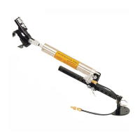
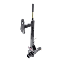
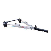
7. Now move the braking system forward until cylinder is fully collapsed.
8. Make sure the unit is approximately level. Adjust the feet on the bottom of the braking system making sure
that all four feet are making contact with the floor of your vehicle.
IMPORTANT! Once level, make sure lock nuts are tightened to secure feet. Feet may be
removed if necessary or for fit options use feet extender parts #9337 & 9337-4 found in the optional
equipment section featured later in this manual.
IMPORTANT! The braking system must be close to level to operate properly.
9. Loosen knob on back of the unit to adjust seat pad up or down as necessary to match seat height.
Note: Adjustable seat pad may be rotated 180 degrees or removed for better fit. There are also two anchor
holes that the adjustment knob may be threaded into for additional fit adjustment
10. Now slide seat forward against the braking system adjustable seat pad. Once again, be certain the unit is
not depressing brake pedal.
Figure 2a Figure 2b Figure 2c
Place cord lock over 12 volt plug Place plug into socket Press cord lock into outlet firmly
cord lock
cord lock
cord lock
Make sure you bend the five tabs on the pedal clamp to
tighten around your brake pedal securely. If loose the pedal
clamp can get out of position and hold the brakes in the on position even when not
braking. This would result in non-warranty brake damage.
CAUTION:
!
inside
tab
tabs
5 clamp tab locations
Figure 2