6
Installation of BrakeAway System
Determine if you will be using the included
BrakeAway System.
Visit www.roadmasterinc.com/laws.htm to see if
a breakaway is required in your state. Roadmaster
strongly recommends that you always use the BrakeAway
System even if it is not required in your state or country.
The BrakeAway kit is an integral part of the braking system
and should always be installed. Roadmaster strongly
recommends that you install and use the BrakeAway.
If you choose not to use the BrakeAway, Roadmaster will not be
held responsible for any property damage, personal injury or
liability that results.
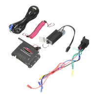
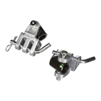
a.) Mount the Breakaway switch to a metal surface (not plastic) on the car near the driver's side front of the vehicle. Make
sure that the mounting location can be easily accessed. The Breakaway switch must be installed in a horizontal
position that allows the Breakaway pin to point toward the motorhome. Be sure the install location allows the
Breakaway pin to pull freely away from the car without any obstruction.
Do not attach the Breakaway switch to the brackets or the tow bar. If the tow bar or
bracket fails, the BrakeAway will separate with the bar or bracket preventing the
Breakaway switch from activating.
WARNING:
!
HELPFUL HINT! If you install the Brake-Lite Relay Kit number 88400, your brake lights will not come on
unless the ignition switch is turned on. Therefore, always turn on the ignition switch when checking for
brake lights. Manually depress the brakes to verify the brake lights are working.
18 a.) Turn ignition on. Do not start the vehicle, but make sure that the ignition is in the "ON" position, NOT the
"ACCESSORY" position.
b.) Go to the rear of the vehicle and see if brake lights are on. If so, DO NOT TOW. You must reposition the
unit as its current position will cause the brakes to be on all the time. After repositioning, check the brake
lights again. Now reprogram level (see step 14).
c.) Now have someone push and hold the test button so that the Portable Braking System will activate. The
brake lights should come on. This step is just to verify that your brake lights are functioning properly.
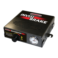
IMPORTANT! The Brake Alert transmitter will alert you when the unit cylinder is extended, not
necessarily when the brake pedal is being depressed. The system includes Brake Pedal Monitor Kit #9333
will illuminate the transmitter when the brake pedal is being depressed regardless of if the cylinder is
extended such as when the seat is too far forward forcing the unit closer to the brake pedal.
Refer to “Brake Pedal Monitor Wire Kit #9333 installation instructions later in this manual.
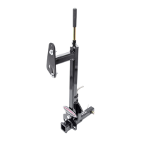
Make sure the system is not depressing the brake pedal. If the unit is
positioned improperly, or if the seat is too close, then the system will cause
continual braking resulting is severe non-warranty brake damage. Once
installed, follow the steps below to make certain that the unit is positioned correctly.
WARNING:
!
Installation continued
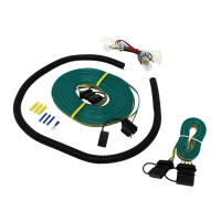
b.) Start in front of the car on the driver's side. Carefully route the wire through the firewall using a pre-existing hole if
possible. If not, drill a 1/2" size hole. Cut the included grommet on one side and place around the wire and then
insert the included grommet in firewall. Feed the remaining wire through the grommet and carefully route the wire
through the engine compartment to the inside of the car where the wire is within reach of the Breakaway switch.
Avoid wire placement near moving parts or hot areas of the engine as this will cause non-warranty failure.
Seal grommet with silicone sealer (not included).
Installation continued
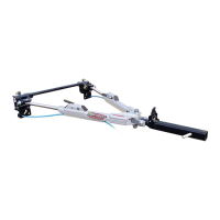
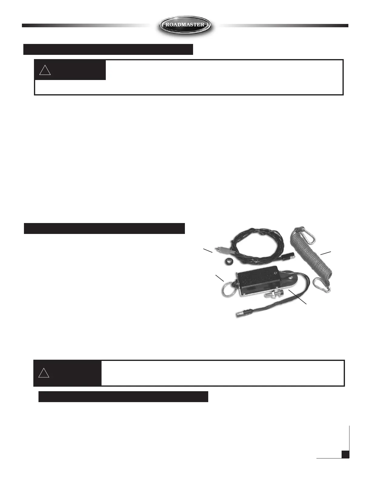
Wiring harness with
blue RCA
connector
Part #650899
Breakaway
switch
Part #650898
Cable
Part #8602
Breakaway
pin