Part no. CB-209-1428 08/11/22
© 2022 Robern, Inc. 701 N. Wilson Ave. Bristol, PA 19007 U.S.A.
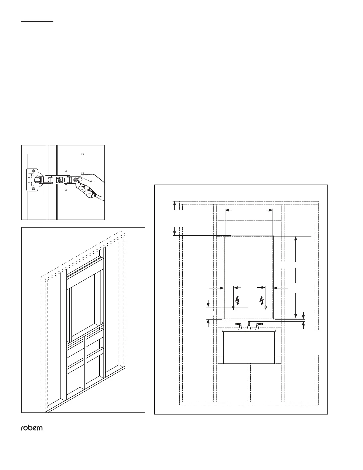
These instructions are for recess mounting your cabinet. Make rough opening and frame on all sides. Find the specic model
dimensions to make rough opening (page 5).
Ensure that the cabinet is mounted so that the door has at least 1" (25mm) clearance from the top of the faucet and at least 1" (25mm)
clearance from the ceiling.
1. Before beginning installation remove and set the door aside in a safe place. Remove door from cabinet by unclipping the hinges from
the mounting plates.
2. Electrical Option Cabinets: Provide a separate electrical connection for electrical options and lighting. Pull electric wire through the
hole. Be sure to provide enough wire to make proper and safe connections to the cabinet.
5
rrev. 11/13/2018 © 2018 Robern, Inc.209-1177-F M SERIES CABINET W/ SAFESEAL GASKET 800.877.2376 www.robern.com
If an electrical opon is provided, all wiring should
be done by a qualied licensed electrician.
WARNING: To reduce the risk of electrical
shock, shut o power before wiring the cabinet.
CAUTION: Requires 120 VAC 20 Amp
circuit. Up to 4 cabinets can be wired to a
dedicated circuit.
CAUTION: This product must be connect-
ed to a grounded, metal permanent wiring
system or an equipment-grounding conduc-
tor must be run with the circuit conductors
and connected to the equipment grounding
terminal or lead on the product.
WARNING: An Electrical opon cabinet
must be wired to a 20 Amp GFI (Ground
Fault Interrupter) protected circuit when
used in bathrooms and all other locaons
required by the Naonal Electric Code.
CAUTION: Maximum shelf load 34 LBS
1. Unplug the door from the cabinet.
2. While supporng the door, reach around
to the back of the hinge and pinch the lever
towards you to release the latch. Carefully
slide the door o.
3. Remove the access screws at the boom
of the outlet shelf. Remove lens by gently
prying up on the front edge of the lens, then
liing up and out. Remove outlet shelf for
access to electrical connecons by pulling
boom towards you, then liing up.
4. Feed electric wire through access hole
in the back of cabinet. Space inside outlet
shelf is at a premium; be sure to keep eld
wire length to a minimum.
Si une opon électrique est fournie, tout le lage
doit être fait par un électricien qualié et licencié.
AVERTISSEMENT : Pour réduire le risque de
choc électrique, couper l’alimentaon avant de
procéder au lage de l’armoire.
AVERTISSEMENT : Nécessite un circuit de 20
ampères à 120Vca. On peut brancher jusqu’à 4
armoires sur le circuit.
AVERTISSEMENT : Ce produit doit être branché
dans un système de câblage en métal permanent et
mis à la terre adéquatement, ou un conducteur de
mise à la terre doit être couru avec les conducteurs
du circuit et raccordé au terminal de mise à la terre de
l’équipement ou sur la borne appropriée sur le produit.
AVERTISSEMENT: Une armoire à opon
électrique doit être câblée à un circuit protégé par
un GFI (disjoncteur de fuite de terre) de 20 ampères
si elle est ulisée dans des salles de bain et dans
tous autres emplacements requis par le Naonal
Electric Code (Code électrique naonal).
AVERTISSEMENT: Tabelee poids maximum
15.4 KG
1. Débranchez la porte de l'armoire.
2. Tout en soutenant la porte, aeindre autour de
l'arrière de la charnière et pincer le levier vers vous
pour libérer le verrou. Rerez délicatement la porte.
3. Rerer les vis d'accès dans le bas de l'étagère
avec la prise. Rerer la lenlle en soulevant avec
précauon le bord avant de celle-ci, puis en la levant
pour la faire sorr. Rerer l'étagère avec la prise
pour accéder aux connexions électriques en rant le
bas de l'étagère vers soi, puis la lever.
4. Alimenter le l électrique par l'orice d'accès
dans l'arrière de l'armoire. L'espace à l'intérieur
de l'armoire avec la prise est à un point primordial;
s'assurer par conséquent de maintenir la longueur
du l in-situ à un minimum.
Si se proporciona una opción eléctrica, todo el
cableado debe ser realizado por un electricista
calicado.
ADVERTENCIA: Para reducir el riesgo de
electrocución, apague la electricidad antes de
conectar el gabinete.
PRECAUCIÓN: Requiere un circuito de 120 VAC
20 Amp. Hasta 4 gabinetes se pueden conectar al
circuito.
PRECAUCIÓN: Este producto debe conectarse a
un sistema de cableado permanente de metal con
bajada a erra o se debe colocar un conductor de
bajada a erra del equipo con los conductores de
circuito y conectarse a la terminal de bajada a erra
del equipo o cable principal del producto.
ADVERTENCIA: Un gabinete opción eléctrica
debe estar conectada a un circuito de 20 amperios
protegido GFI (Interruptor de falla a erra) cuando
se usa en baños y todas las demás ubicaciones
requeridas por el Código Eléctrico Nacional.
PRECAUCIÓN: empo máximo de conservación
carga 34 libras
1. Desconecte la puerta del armario.
2. Mientras sosene la puerta, toque la parte trasera
de la bisagra y pellizque la palanca hacia usted para
soltar el pesllo. Deslice cuidadosamente la puerta.
3. Rere los tornillos de acceso en la parte inferior
del estante con enchufe. Haga palanca hacia arriba
en el borde delantero de la lente para rerarla,
luego levántela y sáquela. Jale la parte inferior del
estante con enchufe hacia usted, y luego levántelo
para rerar el estante y así obtener acceso a las
conexiones eléctricas.
4. Pase el cable eléctrico a través del oricio de
acceso en la parte posterior del gabinete. El espacio
dentro del estante con enchufe es restringido;
asegúrese de mantener la longitud del cable en el
lugar de instalación a un mínimo.
ELECTRIC OPTION / OPTION ÉLECTRIQUE / OPCIÓN ELÉCTRICA
1-3
32
4
1
 Loading...