4-6
CAMSHAFT
‘I’he camshaft for the D-type engine
is
made
of
special cast iron and camshaft gears are casted
togcther
in
one
piece.
Both
sides
of
the shaft
fit
into the plane bearings
on
the
crankcase and main bearing cover.
‘I’hc
camshaft
for
the
B-type engine
is
made
of
forged carbon stcel and also functions as
PTO
shaft.
The cam gear
is
press fitted
on
the
shaft
and the
ball
bearings arc employed
on
both sides
for
sup-
porting the shaft. (See
Fig.
4-6.)
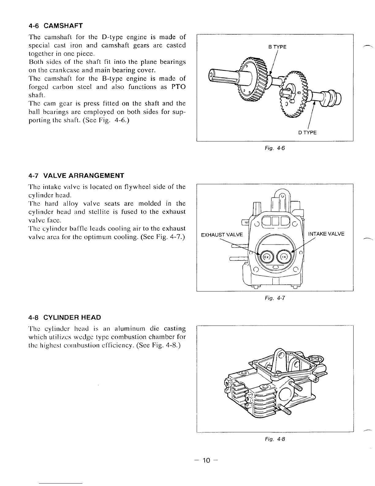
4-7
VALVE ARRANGEMENT
‘I’he intake v;llve
is
located
on
flywheel side
of
the
cylinder hcad.
‘I’hc
hard
alloy
valvc
seats are molded
in
the
cylinder head and stcllite
is
fused
lo
the exhaust
valvc
f;KC.
‘I’hc
cylindcr
bafflc
leads cooling air to the exhaust
valvc
arca
for
the optimum cooling. (See Fig.
4-7.)
4-8
CYLINDER HEAD
‘I’hc cylindcr hcad is
a11
aluminurn die casting
which utilizcs
wcdgc
type combustion chamber
for
thc highcst
combusl.ion
cli‘icicncy. (See Fig.
4-13,)
I
B
TYPE
I
I
D
li’PE
Fig.
4-6
Fig.
4-7
h.
Fig.
4-8
-
10
-