– English
14 Silverline - PS 3200 V0713
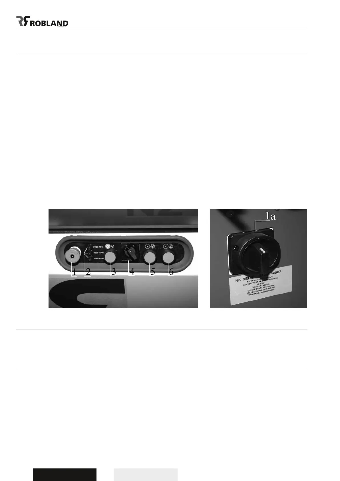
Starting up the machine (PS Version)
Turn the main switch (6.1) to “1” and ensure that the star-delta switch (4) is put in position “star”.
- To start the main saw motor push the start button (3).
- After about 8 seconds put the star-delta switch (4) in position “delta”. This time delay is needed to
let the motor gain its full speed before switching over to “delta”. When you forget to switch over from
“star” to “delta”, the motor will reach its full speed but will have no power and will be damaged.
- The scorer motor is started by pushing the start button (6); this is only possible with the main saw
motor running.
- By pushing the stop button (5) the scorer motor is stopped, when the emergency stop button (1) is
pushed both motors are stopped.
- The main saw motor is equipped with an automatic brake which slows down the motor within 10
seconds as soon as the machine is shut off.
wArning:
When the machine access door is open, it is impossible to start up the machine.
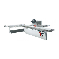
The RPM indicator lights at the front of the main switch panel show the speed of the saw
spindle as soon as the machine is switched on with the main switch (1).
All fuses can be found inside the electrical switch panel and each time this panel is opened the
machine has to be disconnected from its power supply.
Calibration of the scale on
the parallel fence (Fig.25)
Each time a new sawblade is tted the parallel fence scale has to be calibrated to the new
sawblade.
By cutting a sample and measuring its exact length, the scale can be adjusted so that the exact
measure corresponds with the front side of the fence.
After the screw (1) has been loosened the scale can be adjusted. To avoid the fence contacting the
sawblade while it is revolving, the stop ring (2) has to be adjusted.
Slide the fence to about 10 mm from the sawblade.
Now slide the stopring (2) across the round guide bar (3) until it comes up against the
casting of the fence. Tighten the lock screw on the stop ring.
Fig.5 Fig.6