Heating engineer
18
3
2.5.1 Axial gas unit heaters
For axial gas unit heaters the following support brackets
are available as optional:
▶
O19800020 revolving wall support bracket (M20, M25
models)
▶
O19800024 revolving wall support bracket (M30 mod-
el)
▶
OKMN000 swivel bracket (models M35, M36, M40)
▶
O19800026 revolving wall support bracket (M50 mod-
el)
▶
O19800028 revolving wall support bracket (M60 mod-
el)
▶
OSTF009 support bracket 1,4 m length
▶
Tubular bracket OSTF005
All support brackets are supplied with bolts and the rear
support plate.
For mounting instructions of the brackets, refer to the rel-
evant instruction sheets.
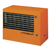
2.5.2 Centrifugal gas unit heaters
For centrifugal gas unit heaters, the following mounting
brackets are available as optional:
▶
OSTF009 support bracket 1,4 m length
All support brackets are supplied with bolts and the rear
support plate.
For mounting instructions of the brackets, refer to the rel-
evant instruction sheets.
3 HEATING ENGINEER
3.1 WARNINGS
3.1.1 General warnings
Read the warnings in Chapter III.1
p. 4
, pro-
viding important information on regulations and
on safety.
Compliance with installation standards
Installation must comply with applicable regula-
tions in force, based on the installation Country
and site, in matters of safety, design, implementa-
tion and maintenance of:
heating systems
gas systems
ue gas exhaust
ue gas condensate discharge
Installation must also comply with the manufactur-
er's provisions.
3.2 FUEL GAS SUPPLY
3.2.1 Gas connection
▶
1/2" M (models M20, M25, M30, M35, M36, M40)
▶
3/4" M (M50, M60 models)
on the rear, to the left (see dimensional diagrams,
Paragraph 1.2
p.8
).
▶
Install an anti-vibration connection between the ap-
pliance and the gas piping.
3.2.2 Mandatory shut-o valve
▶
Provide a gas shut-o valve (manual) on the gas supply
line, next to the appliance, to isolate it when required.
▶
Provide a three-piece pipe union.
▶
Perform connection in compliance with applicable
regulations.
3.2.3 Gas pipes sizing
The gas pipes must not cause excessive pressure drops
and, consequently, insucient gas pressure for the
appliance.
3.2.4 Supply gas pressure
This appliance is equipped for a maximum gas
supply pressure of 50 mbar.
The appliance's gas supply pressure, both static and dy-
namic, must comply with Table 3.1
p.18
, with tolerance
± 15%.
Non compliant gas pressure (Table 3.1
p. 18
)
may damage the appliance and be hazardous.
Table3.1 Network gas pressure
Gas supply pressure [mbar]
Product
category
Countries of destination G20 G25 G25.1 G25.3 G2.350 G27 G30 G31
II
2H3B/P
AL, BG, CH, CY, CZ, DK, EE, FI, GR, HR, IT, LT, LV, MK, NO,
RO, SE, SI, SK, TR
20 30 30
AT, CH 20 50 50
II
2H3P
AL, BG, CH, CZ, ES, GB, GR, HR, IE, IT, LT, LV, MK, PT, SI,
SK, TR
20 37
RO 20 30
AT 20 50
II
2ELL3B/P
DE 20 20 50 50