Electrical installer
24
4
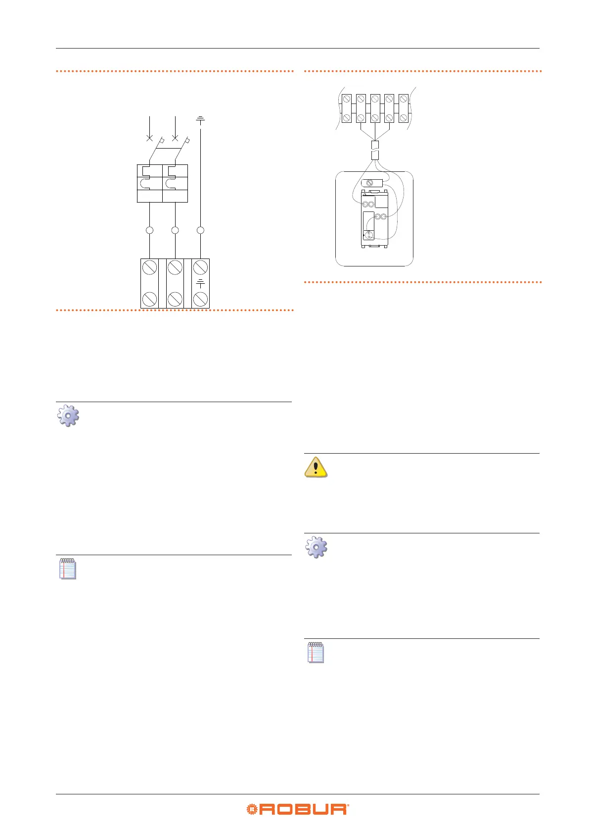
Figure4.1 Appliance connection to the mains power supply
L
N
id id
L
N
4.4 CONTROL SYSTEM
4.4.1 OCDS012 1-key basic control
A basic 1-button command OCDS012 is supplied with the
unit.
How to connect the OCDS012 1-key basic con-
trol
The control must be installed on the wall in a suita-
ble position, using expansion screws.
1. Access the connection terminal block according to
Procedure 4.2
p.23
.
2. Use 3x1 mm
2
cable for connection.
3. Connect the wires to the terminal block as shown in
Figure 4.2
p.24
.
4. For further information refer to the instruction sheet
supplied with the OCDS012 optional.
The cable may not be longer than 20 metres.
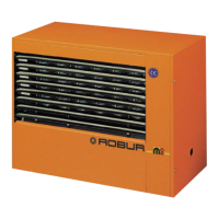
Figure4.2 1-key basic control connection
L1 Lockout lamp
P1 Reset button
3 5 6 7
Z92
L1
P1
5
6
7
L
1
4.4.2 External request
Depending on the required operation, it is required to
arrange:
▶
Request device (e.g. thermostat, timer, switch, ...)
equipped with a voltage-free NO contact, used for
managing start/stop of the gas unit heater.
▶
Request device (switch) equipped with a changeover
contact, for managing winter/summer mode opera-
tion.
For details on the position and possible presence of tem-
porary jumpers on terminals of the unit terminal block,
refer to the wiring diagrams in Paragraph 1.3
p.9
.
All the contacts for external requests of the ter-
minal block in the electrical panel inside the
unit have a 230 V voltage applied to the relative
terminals.
4.4.2.1 Gas unit heater start/stop management
How to connect the external request for gas
unit heater start/stop management
1. Access the electrical board of the appliance according
to the Procedure 4.2
p.23
.
2. Connect the voltage-free contact of the external re-
quest, using a 2x1 mm² cable, to 10-11 terminals of the
terminal block, as shown in Figure 4.3
p.25
.
The cable may not be longer than 20 metres.