Normal operation
30
6
How to change gas
1. Cut o electric power and gas supply.
2. Replace the nozzles on the nozzle manifold of the
burner with those of a diameter suitable for the type
of gas to be used (Table 5.2
p. 29
). Remember to
also mount the copper washers located between the
nozzle and the manifold.
3. Adjust the gas pressure to the burner as indicated in
the 5.2
p.27
Section.
4. Replace the sticker indicating the gas type on the ap-
pliance with the sticker for the new gas type.
6 NORMAL OPERATION
This section is for the end user.
6.1 WARNINGS
General warnings
Prior to using the appliance carefully read the
warnings in Chapter III.1
p. 4
, providing impor-
tant information on regulations and on safety.
First startup by TAC
First start-up may exclusively be carried out by a
Robur TAC (Chapter 5
p.27
).
Never power the appliance o while it is run-
ning
NEVER power the appliance o while it is running
(except in the event of danger, Chapter III.1
p. 4
),
since the appliance or system might be damaged.
6.2 SWITCH ON AND OFF
Routine switching on/o
The appliance may exclusively be switched on/o
by means of the suitably provided control device.
Do not switch on/o with the power supply
switch
Do not switch the appliance on/o with the power
supply switch. This may be harmful and dangerous
for the appliance and for the system.
Checks before switching on
Before switching on the appliance, ensue that:
gas valve open
appliance electrical power supply (main switch ON)
connection and any necessary power supply of the
control device
After a long period of unit inactivity or at the rst
start-up, it may be necessary to repeat the ignition
operation due to the presence of air in the gas
piping.
6.2.1 OCDS012 1-key basic control
Space heating activation
1. Ensure that contact 1-3 is closed by the factory in-
stalled temporary jumper. If a summer/winter selector
switch (Paragraph 4.4.2.2
p. 25
) has been installed,
ensure that the selector switch is in the "winter" posi-
tion (contact 1-3 closed).
2. Close contact Z9 using the control device provid-
ed (thermostat, chronothermostat or voltage-free
contact).
3. After the purge time (around 40 seconds), the gas so-
lenoid valve opens and the burner ignites.
4. When the ame is detected, the control box keeps the
gas valve open.
5. Otherwise, the control unit will try the ignition again
3 times, after the appropriate purge time. If the ame
does not ignite anyway, the control unit locks the unit
and light the locking state indicator lamp (B) on the
control (Figure 6.1
p.30
).
6. In case of ame locking, press the reset button (A).
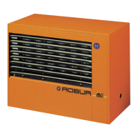
Figure6.1 1-key basic control
A Reset button
B Lockout indicator lamp
Space heating shutdown
1. Switch o space heating request by opening Z9 con-
tact using the provided control device (thermostat,
chronothermostat or voltage-free contact).
2. The burner will shut down, while the fans will contin-
ue to operate until the appliance has cooled down
completely.
In case of prolonged periods of inactivity, see
Paragraph 7.4
p.32
.
Ventilation activation (summer mode)
1. Close the gas valve and check power supply availability