Heating engineer
22
3
details given in Figure 3.8
p.22
.
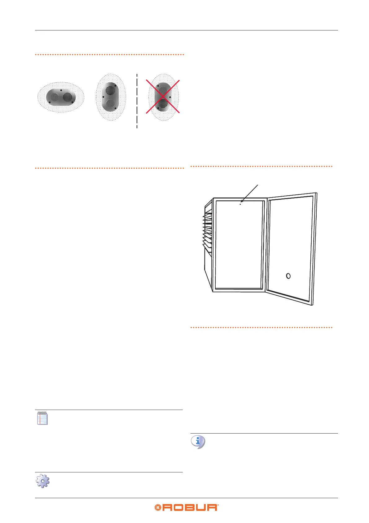
Figure3.8 Wall terminal position
IN combustion air intake
OUT ue gas exhaust
A recommended posi-
tion (OK)
B allowed position (OK)
C position NOT allowed
(NO)
IN
OUT
IN
OUT
IN
OU
3.3.5 Example of calculation
If a M35 unit equipped with a 50 mm high ue diaphragm
is to be installed, the air/ue system will be realized in the
following way:
▶
3 metres of Ø 110 ue pipe
▶
2 90° Ø 110 elbows attached to the ue pipe
▶
2 metres of Ø 130 air pipe
It is then possible to proceed with the verication calcu-
lation, remembering that the maximum permissible pres-
sure drop is 12 Pa (see Table 3.2
p.21
).
Q.ty Resistance
▶
Ø 110 ue pipe
3 m x 1,7 Pa = 5,1 Pa
▶
90° curve
2 x 3,7 Pa = 7,4 Pa
▶
Ø 130 air pipe
2 m x 0,8 Pa = 1,6 Pa
Total pressure drop = 14,1 Pa
Total pressure drop of the piping system is greater than
the maximum allowed pressure drop (12 Pa), therefore
the installation is not allowed.
The installation can be done if one of the following steps
is taken:
▶
t a ue diaphragm 40 mm high
▶
use the Ø 130 ue pipe
▶
reduce the length in metres of the ue duct
In this case the ue diaphragm cannot be removed, as this
will result in the total pressure drop of the ue system to
be lower than the minimum pressure drop allowed for the
unit.
If the total length of the pipe system exceeds 16
metres, it is advisable to contact the technical ser-
vice Robur by telephone.
3.3.6 Installing the ue diaphragm
One or more smoke diaphragm is supplied with the M se-
ries generators.
How to mount the smoke diaphragm
1. Ensure the appliance is not live.
2. Open the electrical panel door.
3. Loosen the screw which secures the cover (see Figure
3.9
p.22
).
4. Remove the cover.
5. Undo the two lower screws which secure the ue fan
and loosen the two upper screws.
6. Insert the ue diaphragm between the ue outlet
ange and the ue fan ange, so that the holes in the
diaphragm are turned downwards.
7. Make the holes in the diaphragm match with the low-
er holes.
8. Tighten again the lower and upper screws that secure
the ue fan.
9. Replace the electrical panel cover and tighten the x-
ing screw.
Figure3.9 Assembly of ue diaphragm
1 Cover locking screw
3.4 AIR DUCTING
Only models equipped with a centrifugal fan
(M gas unit heater C series) can be combined with air
ducting systems, which can be positioned both on the
air intake (with or without mixing chambers) and on the
delivery.
For this purpose, the delivery outlet of the M gas unit heater
C gas unit heaters is provided with xing anges for the
delivery air ducting.
Refer to the Paragraph 2.4.2.1
p. 17
for the dimensions
of the ange connection.
In order to avoid vibrations (possible source of
noise and mechanical failures), it is advisable to
install anti-vibration connections, easily removable
for maintenance operation, at the connection be-
tween the gas unit heater and the air duct.
Set up the air ducting using a traditional suciently