Features and technical data
Installation, use and maintenance manual – M gas unit heater
9
1
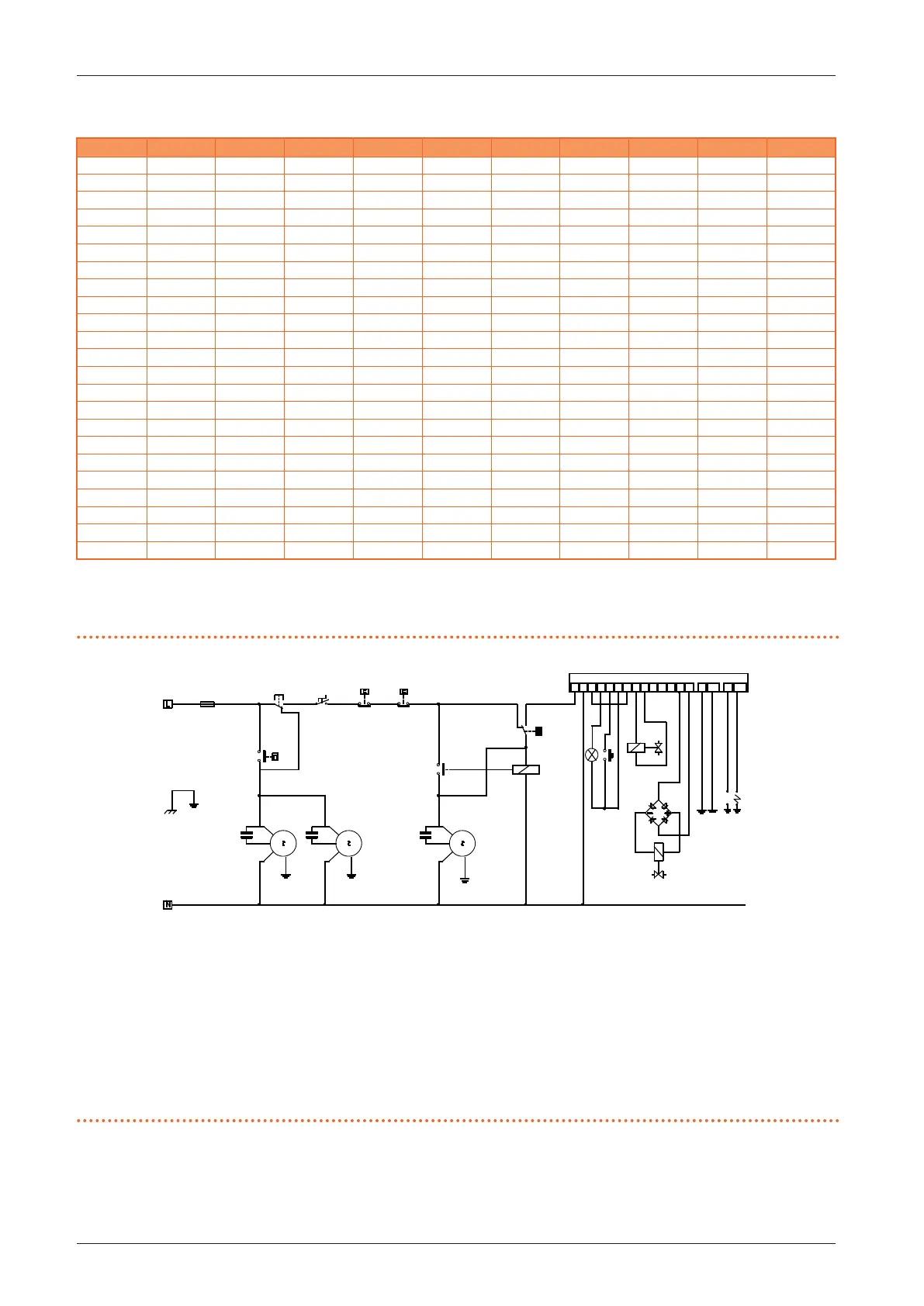
Table1.1 Dimensions
M20 M20 C M25 M30 M30 C M35 /M36 M40 M50 M60 M60 C
A 630 630 630 770 770 880 880 1070 1270 1270
B 631 947 590 624 988 624 643 590 624 988
C 800 800 800 800 800 800 800 800 800 800
D 490 490 490 490 490 490 490 490 490 490
E 370 370 370 510 510 620 620 810 1010 1010
F 405 405 405 405 405 405 405 405 405 405
G 440 438 440 580 578 690 690 880 1080 1078
H 430 431 430 430 431 430 430 430 430 431
J 215 215 215 215 215 215 215 215 215 215
L 285 284 285 285 284 285 285 285 285 284
M - 393 - - 393 - - - - 393
N 95 95 95 95 95 95 95 95 95 95
P 390 390 390 460 460 515 515 398 468 468
Q 435 435 435 435 435 435 435 435 435 435
R 340 340 340 340 340 340 340 340 340 340
S 600 600 600 600 600 600 600 600 600 600
T 715 715 715 715 715 715 715 715 715 715
U - 563 - - 580 - - - - 580
V 1/2” 1/2” 1/2” 1/2” 1/2” 1/2” 3/4” 3/4” 3/4” 3/4”
W - - - - - - - 432 495 495
X 113 113 113 113 113 113 113 113 113 113
Y 133 133 133 133 133 133 133 133 133 133
Z 355 300 355 410 324 410 410 355 410 324
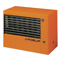
1.3 ELECTRICAL WIRING DIAGRAM
Figure1.3 Operating wiring diagram
CM Fan condenser
CS Extractor fan condenser
L1 Lockout lamp
M Fan motor (2 motors for M50 and M60 models)
M1 Limit thermostat
M10 Internal component protection thermostat
M12 Pressure switch control relay
M2 Fan thermostat
M4 Controller for ignition, adjustment and ame control
M9 Fuse 4,0 A
NP Dierential pressure switch
P1 Reset button
Q1 Gas electrovalve
Q2 Soft opening coil (for M50 and M60 models)
RD Rectier bridge (for M50 and M60 models)
RP7 Ignition electrode
RP8 Detection electrode
S Extractor fan motor
Z1 Summer/winter diverter (not supplied)
Z9 External request (not supplied)
M9
Z1
Z9
M10
M1
RP8
RP7
NP
M12
S
CS
M
CM
M
CM
GND
230V-50HZ
M2
L1
Q2
Q1
RD
M12
P1
1
2
3 4 5 6 7
13
14 15
16
17
18 19
J6
JT1
J5
JT 2
M4