First start-up
Installation, use and maintenance manual – M gas unit heater
29
5
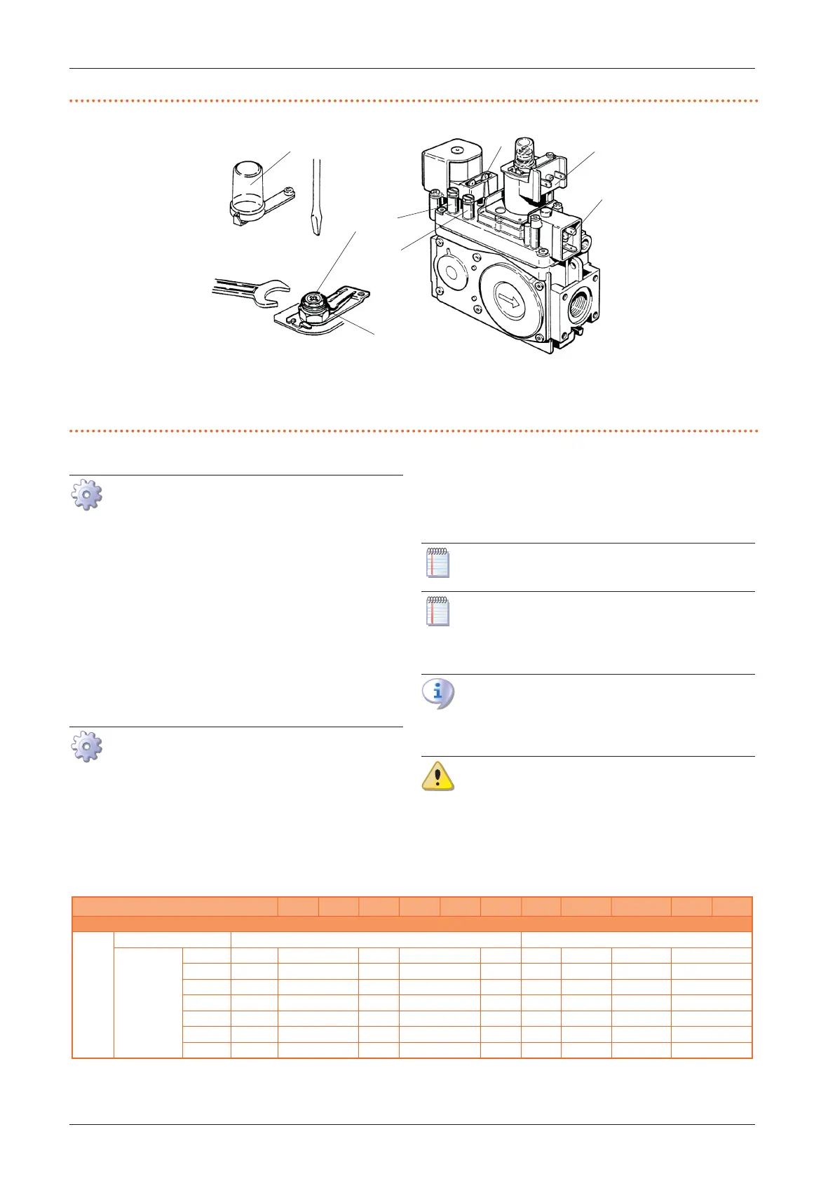
Figure5.3 Gas valve
A Slow opening adjustment
B Burner gas pressure setting screw
C Setting screw cap
D Connector for electrical supply of the soft opening SMD coil
E Inlet gas pressure detection socket
F Outlet gas pressure detection socket
G Electricity supply connectors
A
B
C
E
F
D
5.2.2.2 LPG gas
Figure 5.3
p.29
.
1. Check that the adjusting screw (B) is tightened, oth-
erwise tighten it completely. In this way the pressure
at the burner is directly related to the pressure in the
network.
2. Make sure to have a network pressure of 30 mbar (G30)
or 37 mbar (G31).
3. The reduction of the pressure in the network is possi-
ble with suitable pressure reducers as indicated in the
Paragraph 3.2.6
p.19
.
4. Then adjust the slow opening pressure (Paragraph
5.2.2.3
p.29
).
5.2.2.3 Adjusting the slow opening pressure
Figure 5.3
p.29
.
1. Cut-out the SMD coil supply (D). This will make the
heater attain the soft opening pressure.
2. While holding the nut (B) in place, use the screw (A) to
adjust the slow opening pressure to the value indicat-
ed in the 5.1
p. 28
Table; use a screwdriver for the
operation.
3. Replace the plastic cover C.
4. Restore the SMD coil connection D
5.3 GAS CHANGEOVER
Paragraph reserved exclusively to TACs.
The following instructions apply to both the con-
version from natural gas (G20) to any other gas and
vice versa.
After the gas change operation, carry out the pro-
cedure to adjust the gas pressure to the burner, as
described in Paragraph 5.2
p.27
.
Check that the gas supply line is suitable for the
new fuel type used to supply the unit.
The following Table shows the nozzle diameter and code
for the dierent M gas unit heater models, depending on
the gas type.
Table5.2 Nozzle data
M20 M20 C M25 M30 M30 C M35 M36 M40 M50 M60 M60 C
Installation data
Nozzle
number of nozzles 2 4
Diameter (Ø)
G20 mm 2,80 3,30 4,00 4,50 4,00 3,30 3,45 4,00
G25 mm 2,80 3,30 4,00 4,50 - (1) 3,30 3,45 4,00
G2.350 mm 4,00 4,80 5,20 5,50 - (1) 4,80 5,20 - (1)
G27 mm 3,45 4,00 4,50 4,80 - (1) 3,70 4,00 4,50
G30 mm 1,60/1,80 2,00 2,20 2,40 2,30 1,70/1,95 1,85/2,15 2,20/2,30
G31 mm 1,60/1,80 2,00 2,20 2,40 2,30 1,70/1,95 1,85/2,15 2,20/2,30
LPG mm 1,60/1,80 2,00 2,20 2,40 2,30 1,70/1,95 1,85/2,15 2,20/2,30
(1) The gas unit heater cannot operate with this type of gas.