Heating engineer
20
3
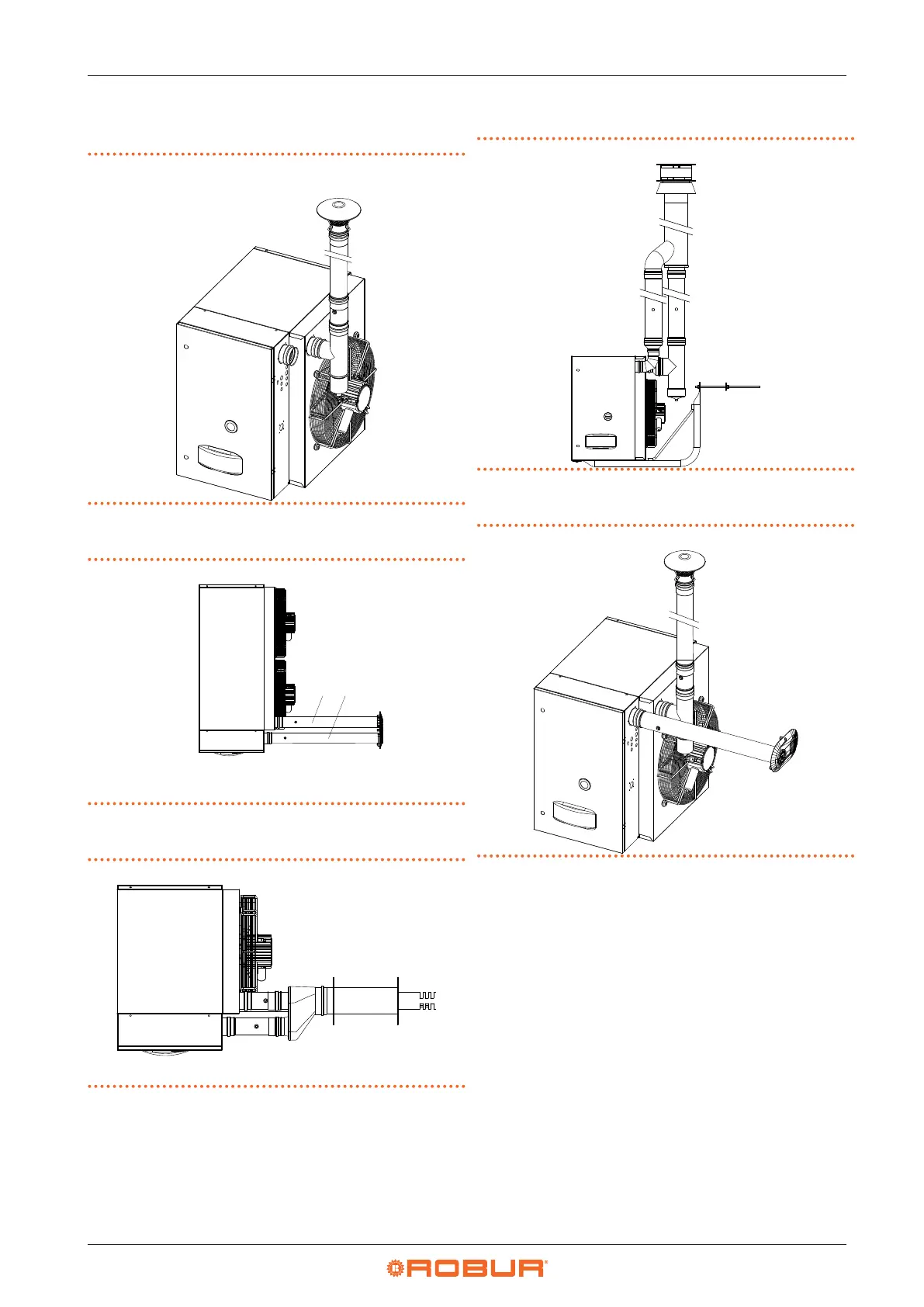
3.3.3.2 B22 type installation with roof ue gas exhaust
pipe
Figure3.2 B22 type installation with roof ue gas exhaust pipe
3.3.3.3 C12 type installation with separate ducts
Figure3.3 C12 type installation with separate ducts
A View from above
1 Flue gas exhaust
2 Combustion air inlet
1 2
3.3.3.4 C12 type installation with wall coaxial terminal
Figure3.4 C12 type installation with wall coaxial terminal
A View from above
A
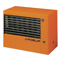
3.3.3.5 C32 type installation with roof coaxial terminal
Figure3.5 C32 type installation with roof coaxial terminal
3.3.3.6 C62 type installation with separate ducts
Figure3.6 C62 type installation with separate ducts
3.3.4 Sizing and installing combustion air/
exhaust fumes ducts
In order to dimension the duct system, the total pressure
drop of the system must be calculated.
The total permissible pressure drop in the pipe system de-
pends on the model of the instrument and any diaphragm
tted (Table 3.2
p.21
).
The pressure drops of the ue and air pipes available as
Robur optional are shown in Table 3.3
p.21
.
The pressure drops of the coaxial pipes available as Robur
optional are shown in Table 3.3
p.21
.
Resistance from the separate terminals are negligible
since they are very low.
In the design phase it is necessary to verify that the sum of
the pressure drops of the pipe system used is lower than
the maximum pressure drop allowed by the device (Table
3.2
p. 21
). The 3.3.5
p. 22
Section provides an exam-
ple of how to calculate the pressure drop.