Normal operation
Installation, use and maintenance manual – Supercromo
19
6
3001 3002
Nozzle
Diame-
ter (Ø)
G20 mm 1,45/1,70
G25 mm 1.75/1,80
G30 mm 0.85/0,95
G31 mm 0.85/0,95
Code
G20 - 53
G25 - 54
G30 - 50
G31 - 50
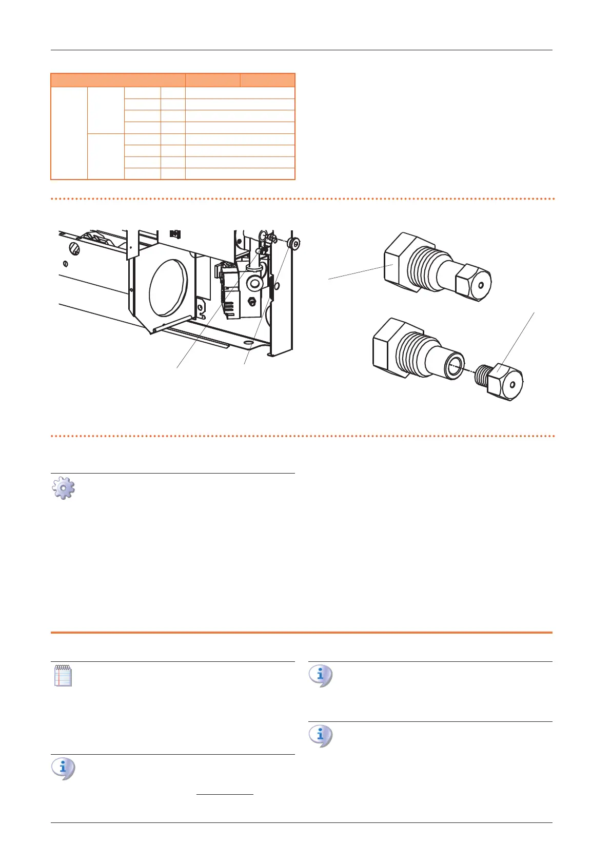
Figure5.2 Detail of burner assembly
A Nozzle holder. B Cap
5.3.2 Conversion from LPG to natural gas
Figure 5.2
p.19
1. Cut o electric power and gas supply.
2. Remove the casing from the frame and disconnect the
casing grounding cable.
3. Unscrew the B plug with a no. 19 wrench.
4. Using a no.10 socket wrench introduced in the open-
ing, unscrew the nozzle holder A.
5. Unscrew the calibrated nozzle C from the nozzle hold-
er A and replace it (Table 5.2
p.18
).
6. Screw the nozzle support and nozzle assembly back
on to the burner.
7. Reassemble the plug B.
8. Turn on the gas-red convector and check the gas
tightness of plug B.
9. Check the gas pressure at the burner as described in
Paragraph 5.2.1
p.17
.
10. Remove the "LPG" adhesive label and replace it with
the "NATURAL GAS" adhesive label.
11. Connect the grounding cable of the casing and reas-
semble the casing.
6 NORMAL OPERATION
This section is for the end user.
The operation of the Supercromo gas-red heaters is con-
trolled by the supplied control panel.
6.1 WARNINGS
General warnings
Prior to using the appliance carefully read the warn-
ings in Chapter III.1
p. 4
, providing important
information on regulations and on safety.
First startup by TAC
First start-up may exclusively be carried out by a
Robur TAC (Chapter 7
p.23
).
Never power the appliance o while it is run-
ning
NEVER power the appliance o while it is running
(except in the event of danger, Chapter III.1
p. 4
),
since the appliance or system might be damaged.