Features and technical data
8
1
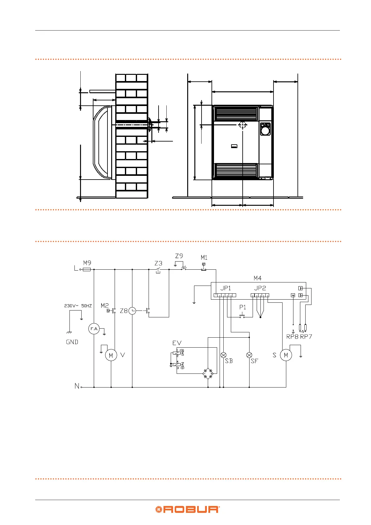
1.2 DIMENSIONS
Figure1.1 Dimensions
173
30
35
49
100
478
100
577
151
239
239
1.3 ELECTRICAL WIRING DIAGRAM
Figure1.2 Wiring diagram for models 3001 and 3002
EV Gas valve (Power supply: terminals 1 and 3 - Serial con-
nection of the coils: terminals 2 and 4)
F.A. Noise lter
L Line
M1 Limit thermostat
M2 Fan thermostat
M4 Control unit
M9 2 A fuse
N Neutral
P1 Reset button
RP7 Ignition electrode
RP8 Detection electrode
S Combustion air blower
SB Red lock-out signal light
SF Green operation signal light
V Fan
Z Manual/programmed switch (present on 3002 model
only)
Z8 Programmable timer (present on 3002 model only)
Z9 Room thermostat
GND Earth