Electrical installer
16
4
Figure3.9 Support bracket detail
A Supports B Fastening screws
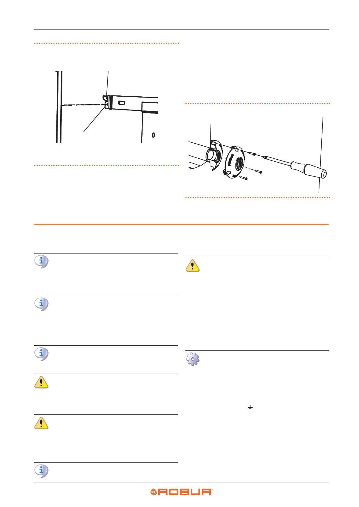
3.5.2 Install the windproof terminal
1. When the appliance is installed, place the alumini-
um windproof terminal to the outdoor wall so that it
engages with the end of the ue gas pipe and mark
the position of the three holes for the expansion plugs
(see Figure 3.10
p. 16
). The terminal must be tted
with the ue outlet grille arranged vertically.
2. Remove the terminal and drill the xing holes (6 mm Ø
for the supplied wall plugs).
3. Reassemble the terminal and secure it with the screws
using the relevant plugs (see Figure 3.10
p.16
).
Figure3.10 Windproof terminal xing
4 ELECTRICAL INSTALLER
4.1 WARNINGS
General warnings
Read the warnings in Chapter III
p. 4
, provid-
ing important information on regulations and on
safety.
Compliance with installation standards
Installation must comply with applicable regula-
tions in force, based on the installation Country
and site, in matters of safety, design, implementa-
tion and maintenance of electrical systems.
Installation must also comply with the manufactur-
er's provisions.
Live components
After placing the appliance in the nal position,
and prior to making electrical connections, ensure
not to work on live components.
Earthing
The appliance must be connected to an eective
earthing system, installed in compliance with reg-
ulations in force.
It is forbidden to use gas pipes as earthing.
Cable segregation
Keep power cables physically separate from signal
ones.
Do not use the power supply switch to turn the
appliance on/o
Never use the power supply switch to turn the ap-
pliance on and o, since it may be damaged in the
long run (occasional blackouts are tolerated).
To turn the appliance on and o, exclusively use
the suitably provided control device.
4.2 ELECTRICAL POWER SUPPLY
Provide (by the installer) a protected single-phase line
(230 V 1-N 50 Hz).
How to connect the power supply
1. Provide a three-core H05 VVF 3x1 mm² cable with a
maximum external diameter of 8,4 mm by passing it
through hole A and cable gland D and connecting it
to terminal block B (Figure 3.1
p.11
), taking care to
observe the polarity indicated on the terminal block (L
= phase, N = neutral, = earth).
2. Provide the earth lead-in wire longer than live ones
(last to be torn in the event of accidental pulling).
3. The cable shall be tted with a plug at one end or con-
nected to a two-pole switch with a minimum contact
opening of 3 mm.
4. If an external three-pin plug is used, it is advisable to
place a mark on the plug and on the power supply sock-
et, in order to avoid that in case of temporary removal
of the plug, it is reinserted in reverse, with consequent