Heating engineer
Installation, use and maintenance manual – Supercromo
11
3
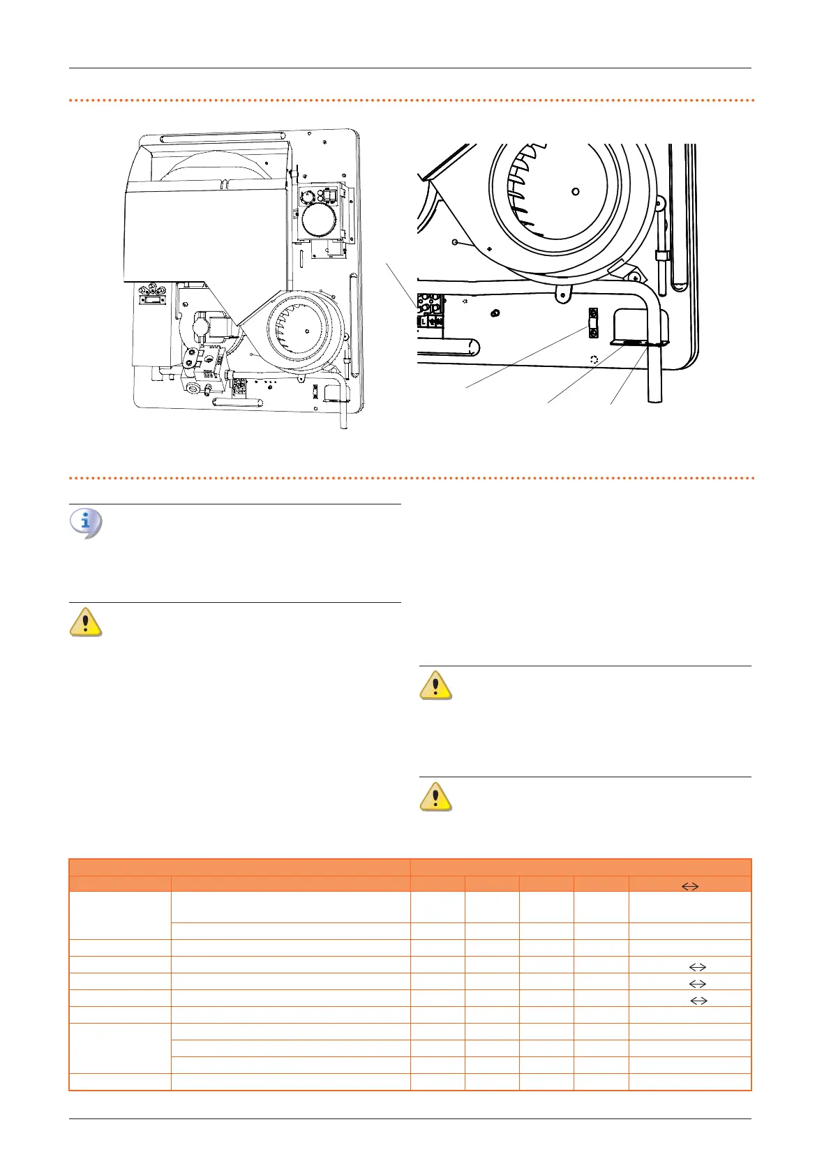
Figure3.1 Gas and power supply position
A Hole for power supply cable
B Terminal block
C Hole for gas pipe
D Cable gland bridge
A
B
C
D
The connection to the gas mains must be made
using a rigid copper or steel pipe and ttings; alter-
natively, a exible stainless steel pipe conforming
to the regulations in force may also be used.
The connection to the gas pipe must be properly
sealed to ensure tightness using a sealant that
complies with EN 751-1 and EN 751-2. The connec-
tion must be made in such a way that no strain is
produced in the pipe or gas-red convector com-
ponents.
3.3.2 Mandatory shut-o valve
▶
Provide a gas shut-o valve (manual) on the gas supply
line, next to the appliance, to isolate it when required.
▶
Provide a three-piece pipe union.
▶
Perform connection in compliance with applicable
regulations.
3.3.3 Gas pipes sizing
The gas pipes must not cause excessive pressure drops
and, consequently, insucient gas pressure for the
appliance.
3.3.4 Supply gas pressure
This appliance is equipped for a maximum gas
supply pressure of 50 mbar.
The appliance's gas supply pressure, both static and dy-
namic, must comply with Table 3.1
p.11
, with tolerance
± 15%.
Non compliant gas pressure (Table 3.1
p. 11
)
may damage the appliance and be hazardous.
Table3.1 Network gas pressure
Gas supply pressure [mbar]
Product category Countries of destination G20 G25 G30 G31 G30 G31
II
2H3B/P
AT, BG, CZ, DK, EE, FI, HR, LT, LV, MK, RO, SE, SI, SK,
TR
20 30 30
AT 20 50 50
II
2H3P
BG, EE, HR, LT, SI, SK 20 37
II
2H3+
CZ, ES, GB, GR, IE, IT, PT, SK 20 28-30 37
II
2Esi3+
FR 20 25 28-30 37
I
3+
FR, BE 28-30 37
II
2H3B/P
HU 25 30 30
II
2E3B/P
LU 20 50
PL 20 37 37
DE 20 50 50
I
2H
LV 20
The appliance gas supply pressure, both static and dynamic, must comply with the values in the Table, with a tolerance of ± 15%.