Heating engineer
12
3
I
3P
NO 30
I
3B/P
MT, CY
30 30
I
3B
30
The appliance gas supply pressure, both static and dynamic, must comply with the values in the Table, with a tolerance of ± 15%.
3.3.5 Vertical pipes and condensate
▶
Vertical gas pipes must be tted with siphon and dis-
charge of the condensate that may form inside the
pipe.
▶
If needed, insulate the piping.
3.3.6 LPG pressure reducers
With LPG the following must be installed:
▶
A rst stage pressure reducer, close to the liquid gas
tank.
▶
A second stage pressure reducer, close to the appli-
ance.
Pressure reducers must always be installed outside
the building.
3.4 COMBUSTION PRODUCTS EXHAUST
Compliance with standards
The appliance is approved for connection to a
combustion products exhaust duct for the types
shown in Table 1.1
p.9
.
3.4.1 Flue gas exhaust and combustion air
intake connection
▶
Ø 50 mm on the rear (Figure 1.1
p.8
)
3.4.2 Installation types
The ue gas exhaust/combustion air intake of the
Supercromo gas-red convectors can be realised in one of
the following ways:
▶
With coaxial pipes with outlet on the installation
wall (maximum pipe length: 1 metre) (see Figure
3.2
p.12
).
▶
With coaxial pipes with 90° outlet (max pipe length: 1
metre) (see Figure 3.3
p.13
). In this case, it is neces-
sary to use the 90° casing for coaxial pipes, available as
OCFF004 optional.
▶
With separate pipes (see Figure 3.4
p. 13
). In this
case, it is necessary to use the separate exhaust casing
available as OCFF002 optional.
Warnings
The installation of pipes with a vertical downward
outlet is prohibited (leads to recirculation of ue
gas with lock-out of the appliance).
It is forbidden to install coaxial pipes with a vertical
outlet upwards (due to rain, water, objects inltra-
tion with consequent lock out of the appliance).
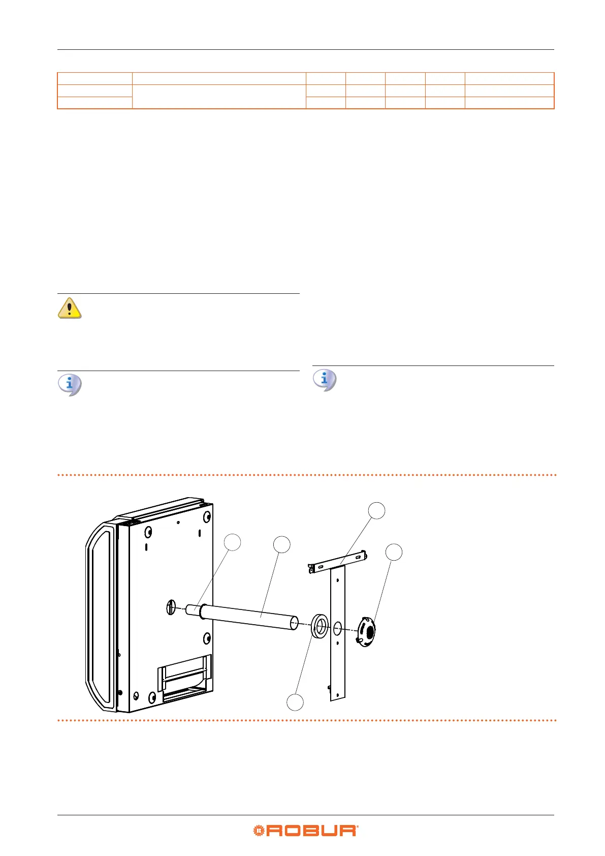
Figure3.2 Installation with straight coaxial pipes
A Air pipe Ø 49 mm
B Flue gas pipe Ø 35 mm
C Adhesive gasket
D Support bracket
E Wall terminal Ø 35 mm
A
B
C
D
E