Heating engineer
Installation, use and maintenance manual – Supercromo
13
3
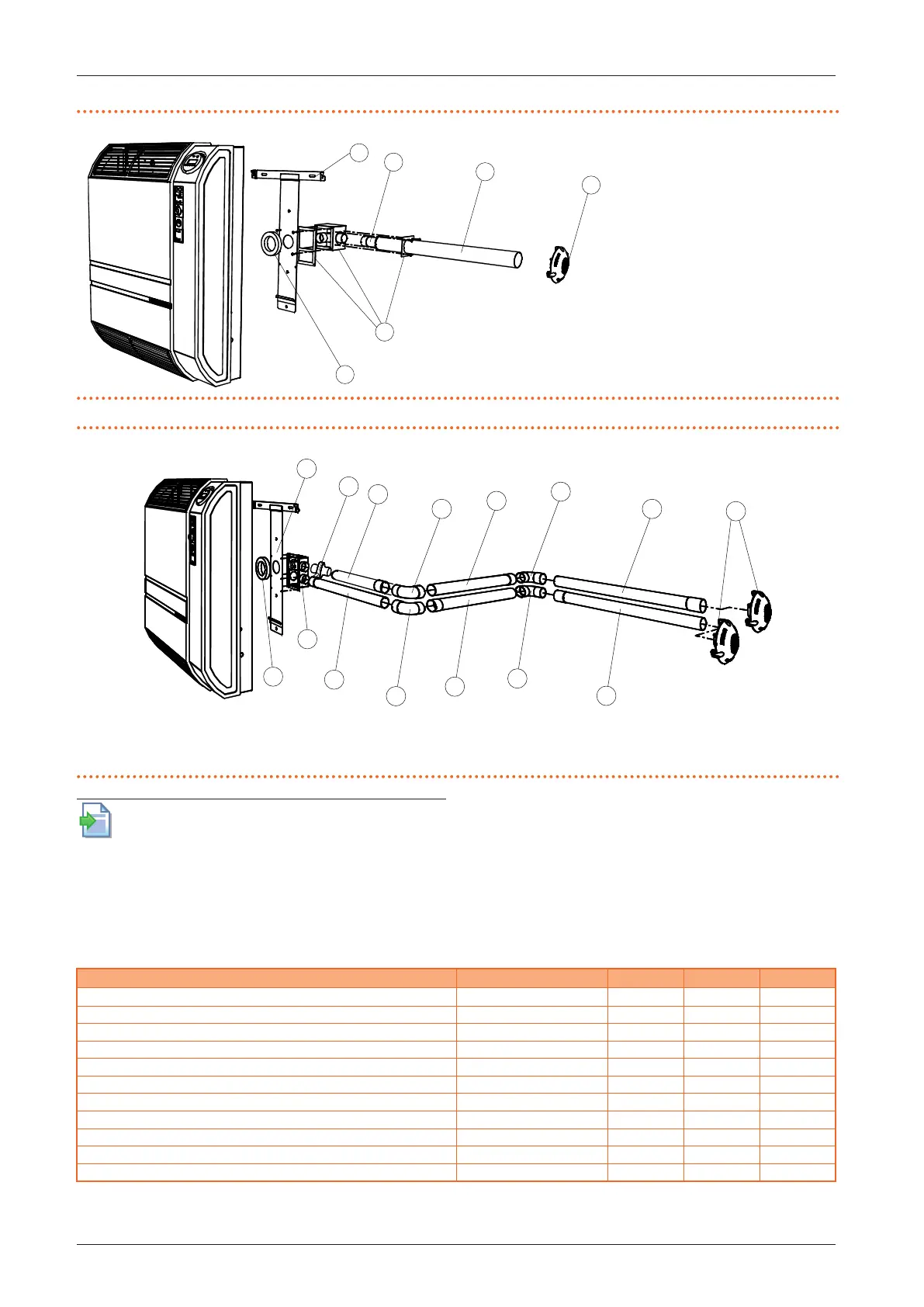
Figure3.3 Installation with coaxial pipes with 90° outlet
A Air pipe Ø 49 mm
B Flue gas pipe Ø 35 mm
C Adhesive gasket
D Support bracket
E Wall terminal Ø 35 mm
F 90° casing for coaxial exhaust
A
B
C
D
E
F
Figure3.4 Installation with wall separate ducts
A Air/ue gas pipe Ø 35 mm
B Elbow 90° M/F Ø 35 mm
C Adhesive gasket
D Support bracket
E Wall terminal Ø 35 mm
F 90° casing for separate exhaust
G Condensate discharge Ø 35 mm
D
A
B
A
A
A
A
B
B
E
F
C
G
For further information on the installation of the
ue gas exhaust/air intake duct, please refer to the
installation guide for the ue gas exhaust/air intake
ducts D-GPP001, available on the Robur website.
3.4.2.1 Installation with separate ducts
If the appliance is installed with separate pipes, suitable
pipes and components, available as optional, must be
used.
At the design stage, it must be veried that the sum of the
pressure drop of all components used does not exceed
the value of the available residual head (Table 3.2
p.13
).
Table3.2 Separate exhaust pressure drop table
Description Code 3001 3002
residual head Pa 25 25
Air pipe internal Ø 33 mm OPRL000 Pa/m 0,6 0,6
Horizontal ue gas pipe internal Ø 33 mm OPRL000 Pa/m 1,5 1,5
Vertical ue gas pipe internal Ø 33 mm OPRL000 Pa/m 0,2 0,2
90° elbow on air pipe OCRV000 Pa 0,6 0,6
90° elbow on ue gas pipe OCRV000 Pa 1,0 1,0
Casing complete with internal elbow for ue gas exhaust OCFF002 Pa 1,5 1,5
Casing without internal elbow for ue gas exhaust OCFF002 Pa 1,0 1,0
Roof terminal Ø 35 mm OTRM002 Pa 0,0 0,0
Wall terminal JTRM000B Pa 0,0 0,0
Condensate discharge Ø 35 mm OSCR003 Pa 0,0 0,0
If the ue gas pipe is longer than 1,5 metres, a condensate drain (available as OSCR003 optional) must be installed