Heating engineer
Installation, use and maintenance manual – Supercromo
15
3
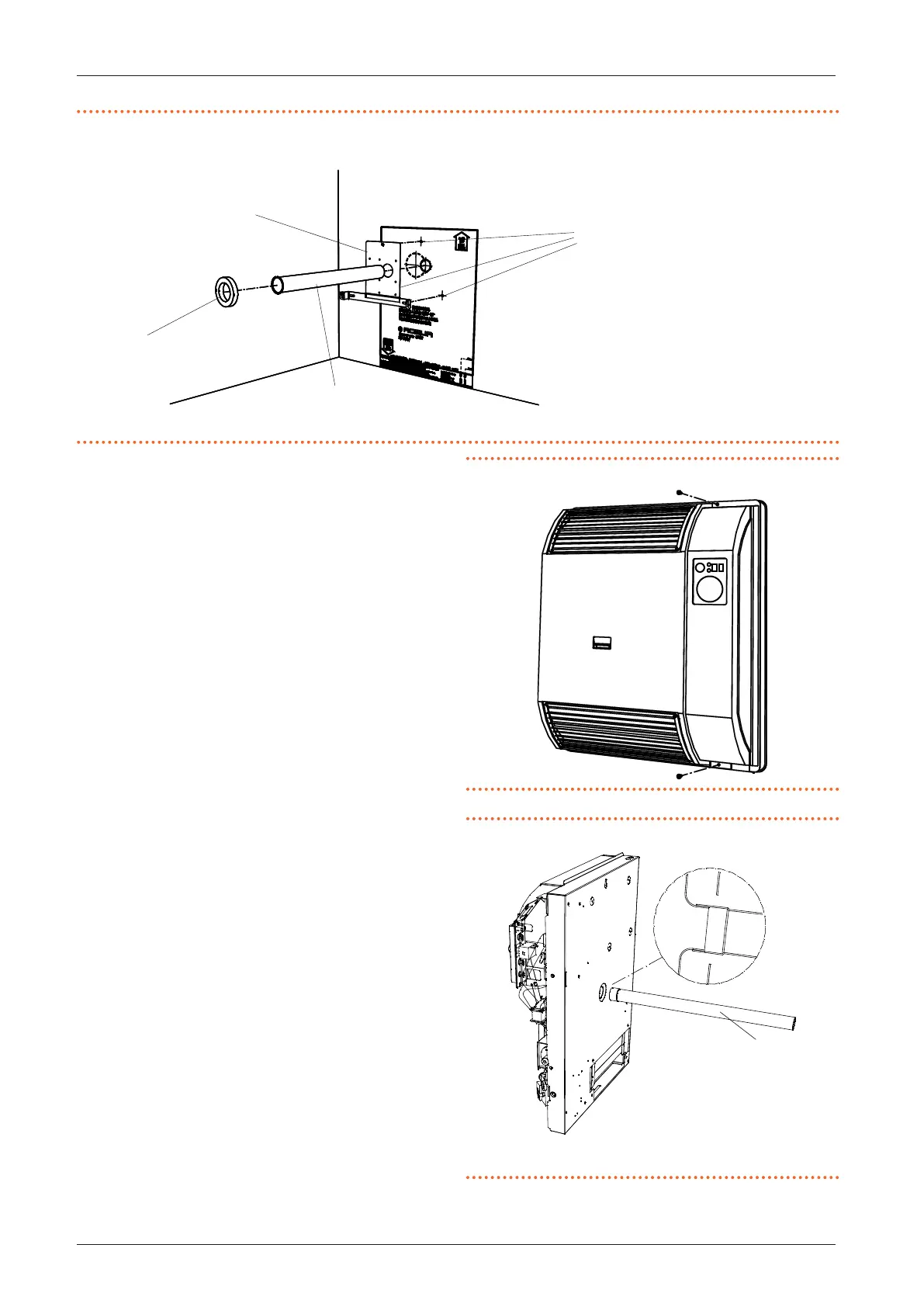
Figure3.6 Support bracket positioning and holes drilling
A Bracket xing holes
B Support bracket
C Adhesive gasket
D Air pipe
B
D
C
7. Position the support bracket and the air intake pipe Ø
49, making sure that the pipe edge perfectly enters the
matching hole in the bracket (see Figure 3.6
p.15
).
8. Fix the support bracket with the screws and position
the round adhesive gasket around the hole in the
bracket (see Figure 3.6
p.15
).
9. Remove the casing from the frame complete with
heating body by loosening the xing screws (see
Figure 3.7
p. 15
) and disconnect the casing earth
cable.
10. Fit the end of the ue gas exhaust pipe (Ø 35 mm)
onto the gas-red convector outlet socket (Figure
3.8
p.15
).
11. Hook the appliance to the appropriate brackets A
(Figure 3.9
p. 16
) by pressing it against the wall.
Secure the heating body to the support brack-
et by means of the two side screws (detail B Figure
3.9
p.16
).
12. Connect the power supply as described in Paragraph
4.2
p.16
.
13. Connect the gas network as described in Paragraph
3.3
p.10
.
14. Connect the grounding cable of the casing and reas-
semble the casing.
Figure3.7 Casing xing screws
Figure3.8 Positioning the ue gas exhaust pipe
1 Flue gas pipe Ø 35 mm
1