78 Rockwell Automation Publication 1766-UM001O-EN-P - September 2021
Chapter 5 LCD and Keypad
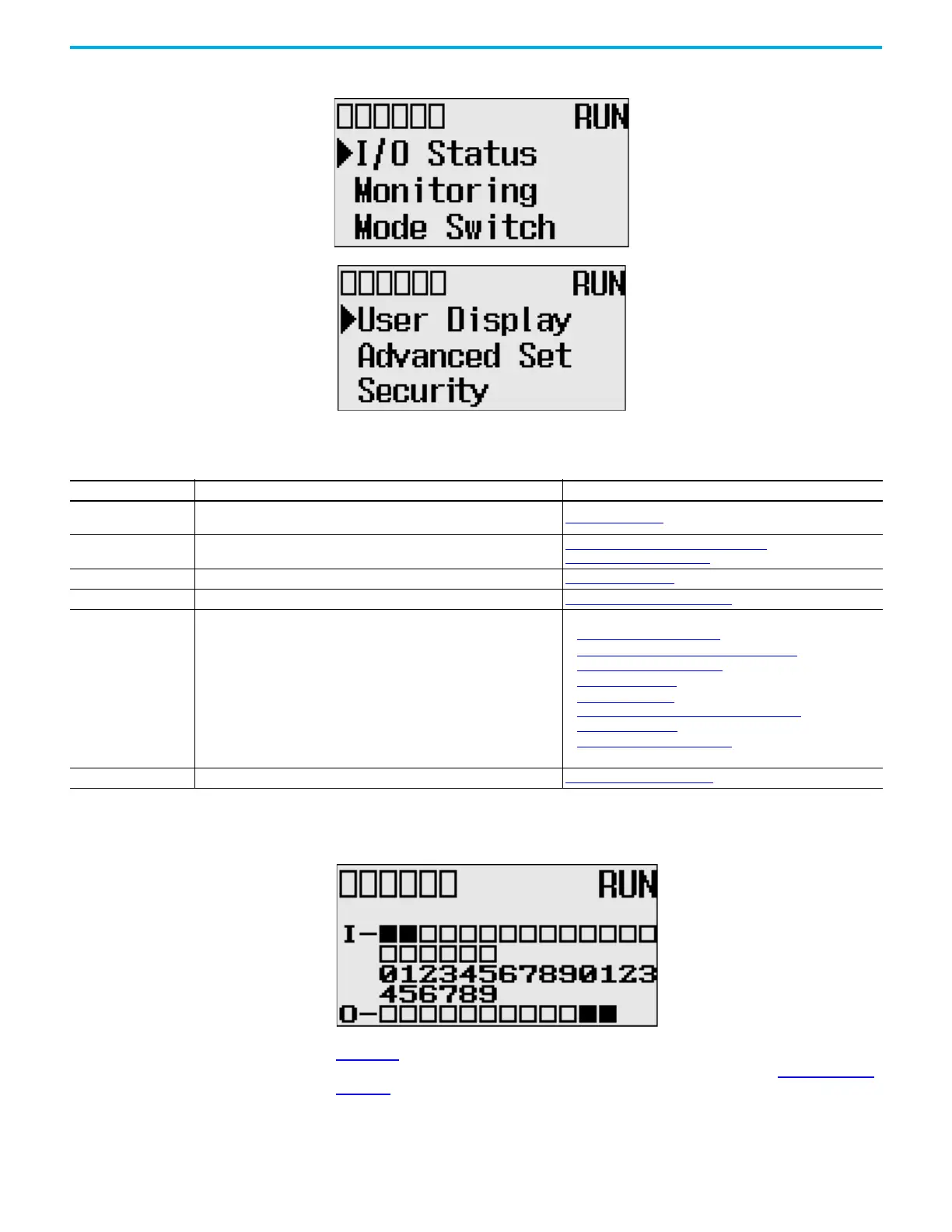
Figure 60 - LCD Main Menu
Note: The Security menu is available in firmware revision 21.000 or later.
Figure 61 - LCD Default Screen – I/O Status Screen
.
Figure 61 is the default screen of the display, allowing you to monitor controller
and I/O Status. For more information on the I/O Status screen, I/O Status on
page 80.
Main Menu Items
Menu Item Description For details, see:
I/O Status
Displays the I/O Status screen, which shows the I/O status of the embedded
digital I/O.
I/O Status
on page 80
Monitoring Allows you to view and change the data value of a bit and an integer file.
Monitor User Defined Target Files on page 82
Monitor Integer Files on page 85
Mode Switch Allows you to change the mode switch selection. Mode Switch on page 94
User Display Displays the user defined LCD screen User-defined LCD Screen on page 96
Advanced Set
Allows you to configure or view the following:
• Change the Key In mode for value entry for a trim pot.
• Use the communications toggle functionality.
• View and change the Ethernet network configuration.
• Change the data value of trim pots.
• View system information, such as operating system series and firmware
version.
• User communication EEPROM functionality.
• Change LCD contrast and backlight option.
• Modbus RTU Slave Node Address
• Change Key In Mode
on page 98
• Communications Toggle Functionality on page 99
• View Ethernet Status on page 99
• Trim Pots on page 107
• I/O Status
on page 80
Save or Load Communication EEPROM on page 111
• LCD setup on page 113
• Protocol Configuration on page 115
Security Allows you to set, activate, deactivate and change the LCD password. LCD Password Setup on page 117
C
OMM0
COMM
1
DCOM
M
B
AT.
L
O
U
-
D
ISP
CO
MM
2
 Loading...


