142 Rockwell Automation Publication 1769-IN088A-EN-P - February 2011
Chapter 3 I/O Memory Mapping
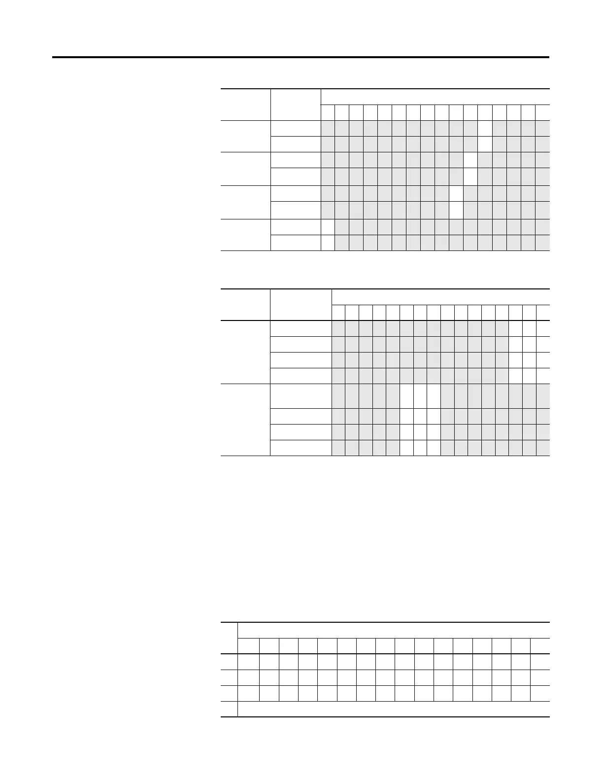
1769-OF8C
The following I/O memory mapping lets you configure the 1769-OF8C module.
Input Data File
For each module, slot x, input data file words 3…10 contain the state of the
module’s output data (output data echo) file words 0…7. During normal
operation, these input words represent the analog values that the outputs are
directed to by the control program.
Enable
Ramping
Disabled 0
Enabled 1
System
Interrupt High
Clamp
Disabled 0
Enabled
(1)
1
System
Interrupt Low
Clamp
Disabled 0
Enabled
(1)
1
Enable
Channel
Disabled 0
Enabled 1
(1) These functions are not supported by all controllers, such as MicroLogix 1500, using any configuration method.
Refer to your controller manual for details.
Define Indicate this These bit settings
1514131211109876543210
Output Range
Select
-10 …+10V DC
000
0…5V DC 001
0…10V DC 010
1…5V DC
011
Output Data
Select
Raw/Proportional
Counts
0 0 0
Engineering Units 001
Scaled for PID 010
Percent Range 011
Define Indicate this These bit settings
1514131211109876543210
Word
Bit Position
1514131211109876543210
0 PFS7S6S5S4S3S2S1S0
1 D3 H3U3O3D2H2U2O2D1H1U1O1D0H0U0O0
2 D7 H7U7O7D6H6U6O6D5H5U5O5D4H4U4O4
3 Channel 0 Data Value
 Loading...


