42 Rockwell Automation Publication IOLINK-UM001A-EN-P - August 2017
Appendix B Message Structure and Configuration Examples
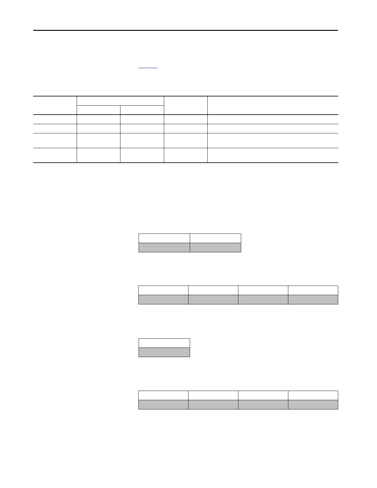
Service Code
Table 2 is used to determine the Service Code that is needed for a specific
Message Instruction.
Table 2 - Service Code
Source Length: from Data Structure Tables
The following tables can be used to determine the source length that is based
on the Service Code that is used and the number of bytes being written.
Table 3 - Read Subindex (4B) - Message Data Format
Source Length= 2 bytes
Table 4 - Read Subindex (4C) - Message Data Format
Source Length= 2 bytes + Number of bytes of data being written
Table 5 - Read Subindex (4D) - Message Data Format
Source Length= 1 byte
Table 6 - Write Index (4E) - Message Data Format
Source Length= 1 byte + Number of bytes of data being written
Service Code (Hex)
Need in Implementation
Service Name Description of ServiceClass Instance
4B Required Required Read Subindex Reads a parameter value from the IO-Link device
4C — Required Write Subindex Writes a parameter value from the IO-Link device
4D Required Required Read Subindex Reads an entire index (all parameters within an index) from the IO-Link
device (uses subindex 0)
4E — Required Write Subindex Writes an entire index (all parameters within an index) from the IO-Link
device (uses subindex 0)
Byte 0 Byte 1
Subindex Number Channel Number
Byte 0Byte 1Byte 2Byte 3
Subindex Number Channel Number Data 0 Data 1
Byte 0
Channel Number = 1 byte
Byte 0Byte 1Byte 2Byte 3
Channel Number Data 0 Data 1 Data 3
 Loading...