16 Rockwell Automation Publication IOLINK-UM001A-EN-P - August 2017
Chapter 2 Set up the 836P Sensor for IO-Link Mode
Example: Set up
the Hardware
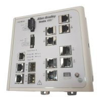
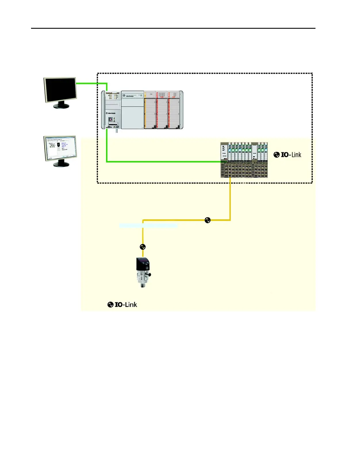
In this example, we are showing an Allen-Bradley® POINT I/O chassis with a
1734-AENTR adapter and a 1734-4IOL IO-Link master module in the first
slot. The 1734-AENTR is communicating with a CompactLogix™ controller
via EtherNet/IP.
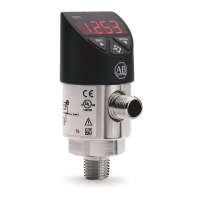
When adding an 836P pressure switch to the 1734-4IOL master module,
complete the following steps:
1. Provide power to the 1734-AENTR adapter.
2. Set the node address on 1734-AENTR adapter.
3. Connect the 1734-AENTR to the controller with the recommended
RJ45 Ethernet cable.
4. Wire the sensor cable to the desired location on the IO-Link master (in
this example, we are showing the sensor that is wired to the channel 0).
5. Connect the 836P to the other end of the sensor cable.
836P
Patchcords (1 pc.) 889D-F4ACDM-2)
 Loading...