6 Micro800 Digital Input, Output, and Combination Plug-in Modules
Publication
2080-WD011A-EN-P - January 2012
Insert Module into Controller
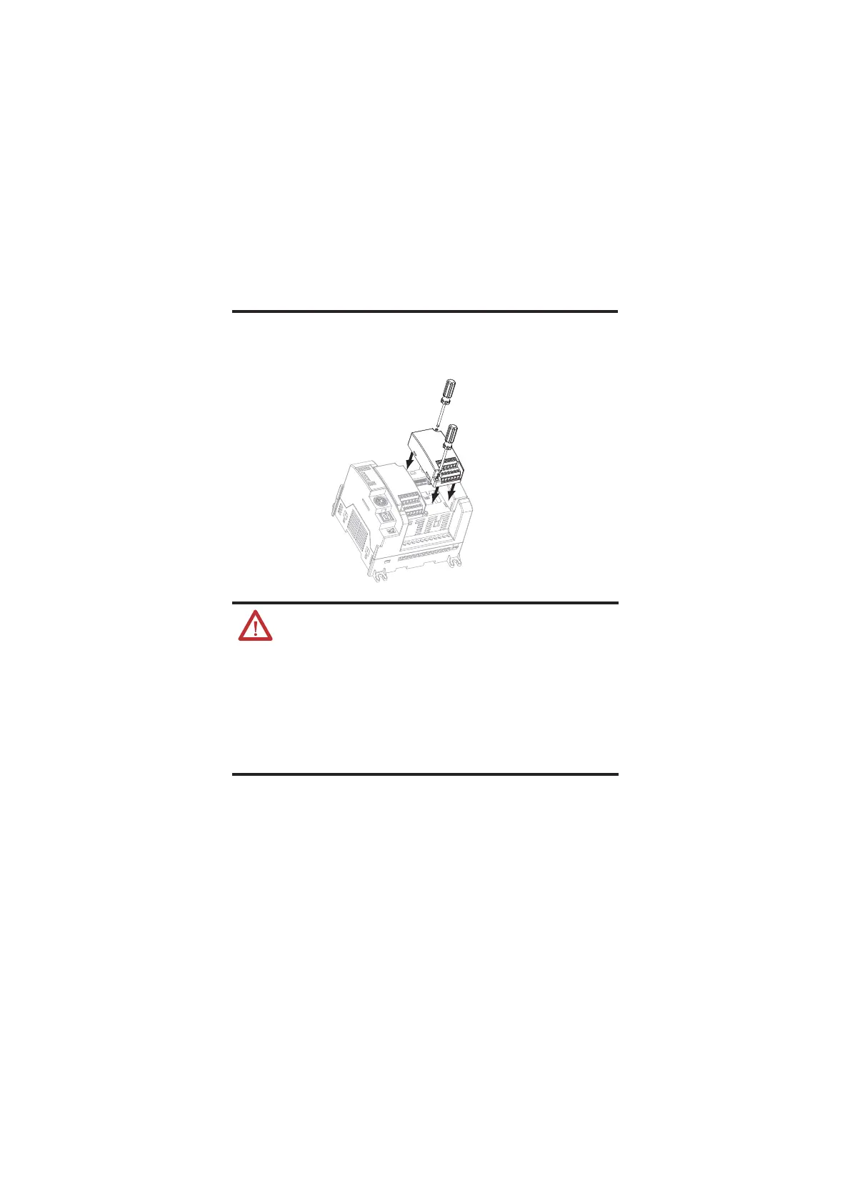
Follow the instructions to insert and secure the plug-in module to the
controller.
1. Position the plug-in module with the terminal block facing the front
of the controller as shown.
2. Snap the module into the module bay.
3. Using a screwdriver, tighten the 10…12 mm (0.39…0.47 in.) M3 self
tapping screw to torque specifications.
WARNING: If you insert or remove the module while the controller
power is on, an electrical arc can occur. This could cause an explosion
in hazardous location installations. Be sure that power is removed or
the area is nonhazardous before proceeding.
WARNING: When used in a Class I, Division 2, hazardous location, this
equipment must be mounted in a suitable enclosure with proper wiring
method that complies with the governing electrical codes.
WARNING: If you connect or disconnect wiring while the field-side
power is on, an electrical arc can occur. This could cause an explosion
in hazardous location installations. Be sure that power is removed or
the area is nonhazardous before proceeding.
45012

 Loading...


