Rockwell Automation Publication 20P-TD001K-EN-P - January 2021 19
PowerFlex DC Drive and Field Controller Technical Data
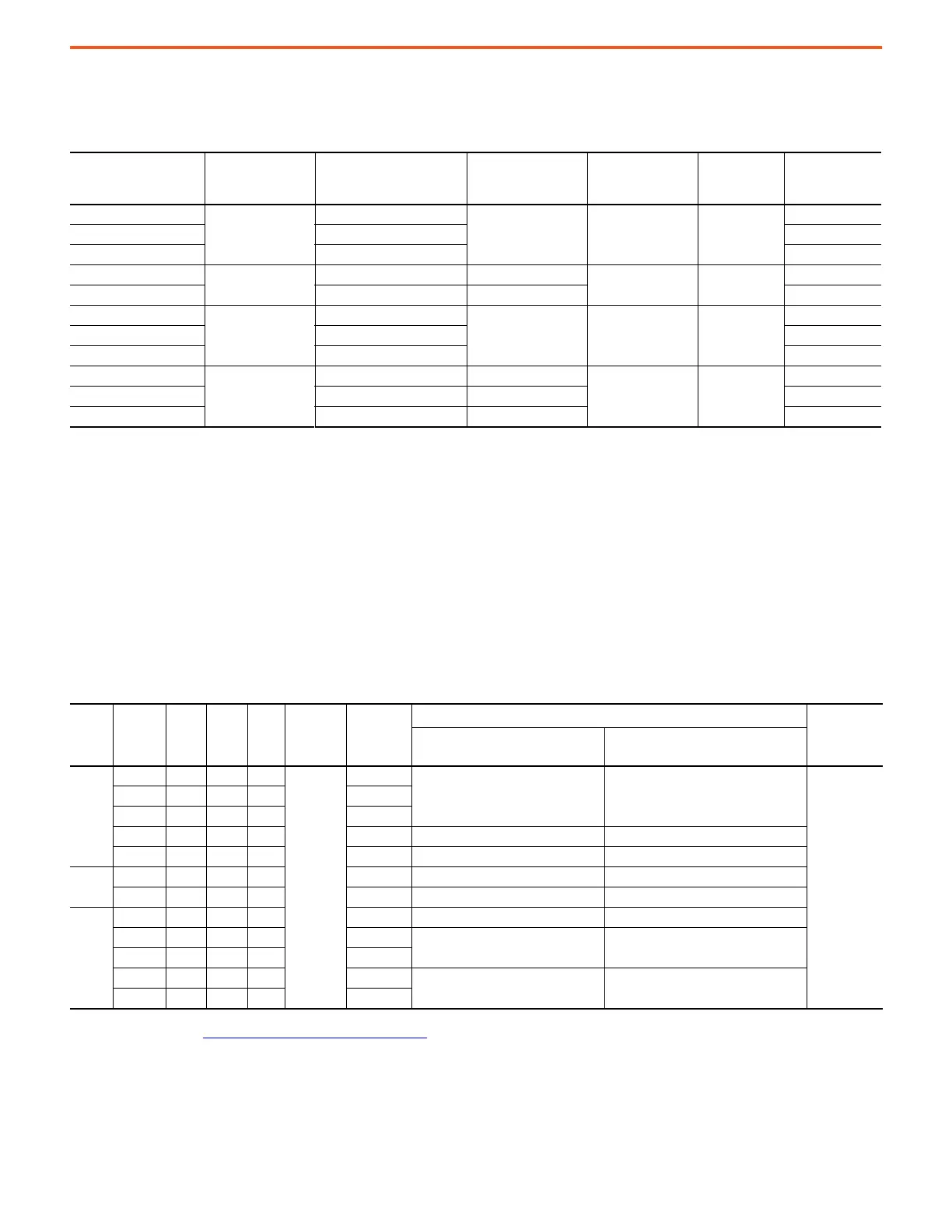
DC Contactor Crimp Lug Kit Specifications
Use the information that is provided in this table to help you order the correct Lug kit for your application.
a
Alternate Dynamic Brake Resistor Kits and DC Output Contactors
The following alternate dynamic brake resistor kits and/or DC output contactors can be used with the corresponding PowerFlex DC drives
but must be sourced separately from the drive.
Rated Motor
Armature Current
(1)
A DC
(1) The Rated Motor Armature Current is taken directly from the motor nameplate or motor data. The current listed in this column is the maximum current that is allowed for the Armature
Conductor Size (column 3) and the DC Contactor Rating (column 2).
DC Contactor Rating
A DC
Armature Conductor Size
(2)
AWG
(2) The armature conductors are sized by multiplying the Rated Motor Armature Current by 1.25 as provided for in NEC 420-22 (1987). The DC lug ratings are determined from NEC Table 310-16
(1987) for copper conductors, insulation temperature that is rated at 75° C (167° F) at an ambient temperature of 30° C (86° F). If conditions are other than shown in NEC Table 310-16, then
refer to application codes.
dB Conductor Size
(3)
AWG
(3) The dynamic braking (dB) conductors are sized as in footnote 2, but at half ampacity due to the short time duration of current flow in these conductors, and has been sized to satisfy NEMA
Standard ICS 3-302.62 - Dynamic Braking. If the load inertia is larger than the motor inertia, calculations must be made to determine correct conductor sizing and dB resistor wattage per
NEMA Standard ICS 3-302.62.
Armature Conductor
Crimp Lug Hole Size
dB Conductor
Crimp Lug Hole
Size
Lug Kit Catalog
Number
4.1…35
56
8
8#10#10
1370-LG40
45…52 6 1370-LG52
55 4 1370-LG56
60…86
110
26
0.25 in. 0.25 in.
1370-LG92
100…110 1/0 4 1370-LG110
129
180
2/0
2 0.3125 in. 0.3125 in.
1370-LG140
146 3/0 1370-LG160
147…167 4/0 1370-LG180
207…218
280
300MCM 1/0
0.5 in. 0.375 in.
1370-LG228
250…265 400MCM 2/0 1370-LG268
266…280 500MCM 3/0 1370-LG280
575V AC Input Drives
Frame
Drive
Current
Rating
Code
DC
Amps
AC
Line
Amps
Hp
Armature
Voltage
(Volts)
dB Resistor
Size
(ohms)
DC Loop Contactor Cat. No.
(1)
(1) Coil voltage = 115V AC, 50/60Hz.
DC Contactor
Crimp Lugs
Cat. No.
(2)
(2) For more information, see DC Contactor Crimp Lug Kit Specifications on page 19.
Drive w/No Dynamic Brake Drive w Dynamic Brake
B
067 67.5 55.1 50
600
5.93
ABB_EHDB220C2P-1L2S ABB_EHDB220C-1L22SS
(3)
(3) Wire and lug size dependent on enclosure dimensions and local codes.
101 101 83 75 3.95
135 135 110 100 2.96
270 270 221 200 1.48 ABB_EHDB360C2P-1L2S ABB_EHDB360C-1L22SS
405 405 331 300 0.988 ABB_EHDB520C2P-1L2S ABB_EHDB520C-1L22SS
C
540 540 441 400 0.741 ABB_EHDB650C2P-1L2S ABB_EHDB650C-1L22SS
675 675 551 500 0.593 ABB_EHDB800C2P-1L2S ABB_EHDB800C-1L22SS
D
810 810 662 600 0.494 ABB_EHDB960C2P-1L2S ABB_EHDB960C-1L22SS
1K0 1080 882 800 0.370
SIEMENS-MFG_14-193-101-58-2 (Qty 2) SIEMENS-MFG_14-193-101-58-2 (Qty 1)
1K2 1215 993 900 0.329
1K3 1350 1103 1000 0.296
CUTLER-HAMMER_6702ED636-2 (Qty 2) CUTLER-HAMMER_6702ED636-2 (Qty 1)
1K6 1688 1379 1250 0.237
 Loading...


