Rockwell Automation Publication 20P-TD001K-EN-P - January 2021 23
PowerFlex DC Drive and Field Controller Technical Data
Field Circuit (Terminals U1, V1)
•230V ±10%, 1Ph
• 400V ±10%, 1Ph
•460V ±10%, 1Ph
Control Circuit (Terminals U2, V2)
• 115V ±15% or 230V ±15%, 1Ph
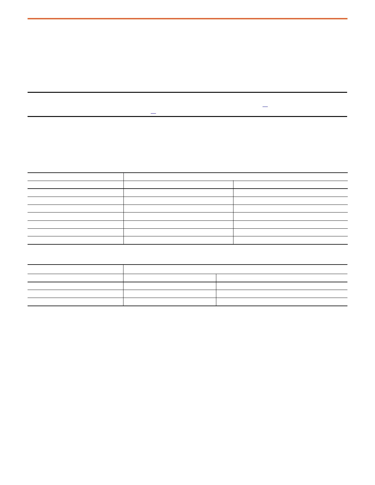
DC Output Voltages
The output voltages that are listed in these two tables take into account an AC input undervoltage within the stated tolerance limits and a
voltage drop of 4% due to an AC input line reactor. It is the same as the rated armature voltage suggested for the connected motor.
IMPORTANT For only frame B and C drives, a jumper must be placed between terminals SA-SB when 115V AC input power is used
for the control circuit. See Frame B Drives SA-SB Terminal Block Location on page 37
and Frame C Drives SA-SB
Terminal Block Location on page 37 for terminal block locations.
Armature Circuit
AC Input Voltage DC Output Armature Voltage (Terminals C & D)
(Terminals U, V, W) Two Quadrant Drive Four Quadrant Drive
230V ±10%, 3Ph 260V 240V
400V ±10%, 3Ph 470V 420V
440V ±10%, 3Ph 530V 460V
460V ±10%, 3Ph 560V 480V
480V ±10%, 3Ph 580V 500V
575V ±10%, 3Ph 680V 600V
690V ±10%, 3Ph 810V 720V
Field Circuit
AC Input Voltage
DC Output Field Voltage
(1)
(Terminals C1 & D1)
(1) The maximum field voltage is equal to 0.85 x AC input line voltage
(Terminals U1 & V1) Fixed Field Adjustable Field
230V ±10%, 1Ph 200V 200V
400V ±10%, 1Ph 310V 310V
460V ±10%, 1Ph 360V 360V

 Loading...


