32 Rockwell Automation Publication 20P-TD001K-EN-P - January 2021
PowerFlex DC Drive and Field Controller Technical Data
PowerFlex DC Drive Armature Voltage Feedback Connections
The armature voltage feedback terminals can be used to monitor the armature voltage of the motor, regardless of the state of a DC
contactor or inverting fault device (fuse or breaker).
If these terminals are not connected to the motor armature, jumpers must be installed between A1 to 1A1 and A2 to 1A2 to allow internal
calculation of motor speed from armature voltage (needed when no speed feedback device is used). If a DC contactor is used without a
speed feedback device present, the drive cannot determine motor speed from the armature voltage feedback signal.
This terminal block is not present on drives that were shipped from the factory before drives with version 3.001 firmware installed. However,
new pulse transformer boards that are shipped as replacement parts from the factory contain this terminal block and can be used with any
version of firmware.
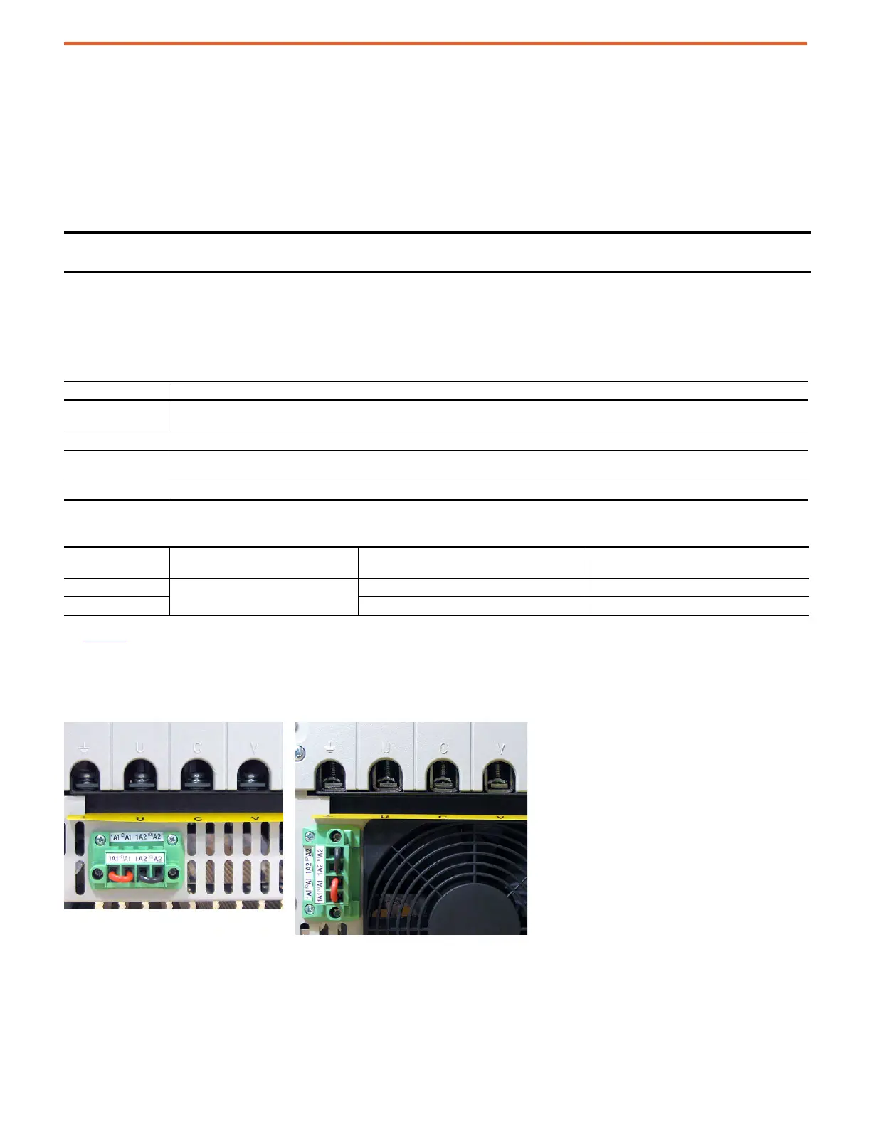
Frame A Armature Voltage Feedback Circuit Terminal Block Location
IMPORTANT By default, these terminals are jumpered - 1A1 to A1 and 1A2 to A2. If these terminals are not wired to the motor
terminals, the jumpers must be installed.
Armature Voltage Feedback Terminals
Terminal Description
1A1
Jumpered to A1 when internal armature voltage feedback is used.
Not used when A1 is connected to motor terminal A1.
A1 Voltage feedback from motor terminal A1.
1A2
Jumpered to A2 when internal armature voltage feedback is used.
Not used when A2 is connected to motor terminal A2.
A2 Voltage feedback from motor terminal A2.
Armature Voltage Feedback Circuit Wire Sizes and Terminal Specifications
Frame Terminals
Wire Size and Type
(1)
(1) Wire with an insulation rating of 600V or greater is recommended. For more information, see Cable and Wiring Recommendations in the PowerFlex Digital DC Drive User Manual, publication
20P-UM001.
Tightening Torque
N•m (lb•in)
A, B & C
1A1, A1, 1A2, A2
24…10 AWG/kcmils 0.5…0.6 (4.4…5.3)
D 22…8 AWG/kcmils 0.8…1.6 (7.1…14.2)
Bottom of View of Drives
Shown with terminals jumpered for internal armature voltage feedback.
Drive with no fan Drive with fan

 Loading...


