36 Rockwell Automation Publication 20P-TD001K-EN-P - January 2021
PowerFlex DC Drive and Field Controller Technical Data
PowerFlex DC Drives and Field Controller Control Circuit Input Power
Supply power to the control circuit through an external 230V AC or 115V AC single-phase power supply. For frames B and C only, a jumper is
required between terminals SA and SB for 115V AC control input power. See Frame B SA-SB Terminal Block Location (on all PowerFlex DC
Drives and Field Controllers) on page 37
and Frame C SA-SB Terminal Block Location (only on PowerFlex DC Drives) on page 37 for terminal
block locations.
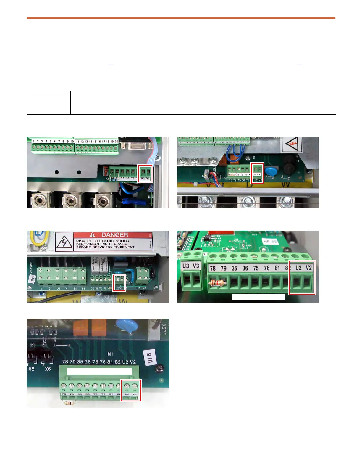
Frames A and B Control Circuit Terminal Block Location (on all PowerFlex DC Drives and Field Controllers)
Frame C Control Circuit Terminal Block Location (only on PowerFlex DC Drives)
Frame D Control Circuit Terminal Block Location (only on PowerFlex DC Drives)
Control Circuit Terminal Designations
Terminal Description
U2
Single-phase AC power for the control circuits.
V2
230V/460V AC Input Frame C 575V/690V AC Input Frame C
Lower, right side of the control
On control pan to the left of the HIM

 Loading...


